LOW COST HOUSING PROJECT
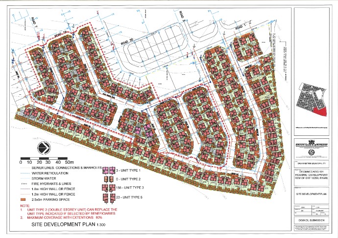
This is a low cost, sustainable housing project that will be built between Paarl and Wellington. It comprises of 181 low cost houses. This was a project that was split between me and Aubrey Langeveldt (50\50) and was our first big project. The section that I was responsible for was the area within the red stippled lines.
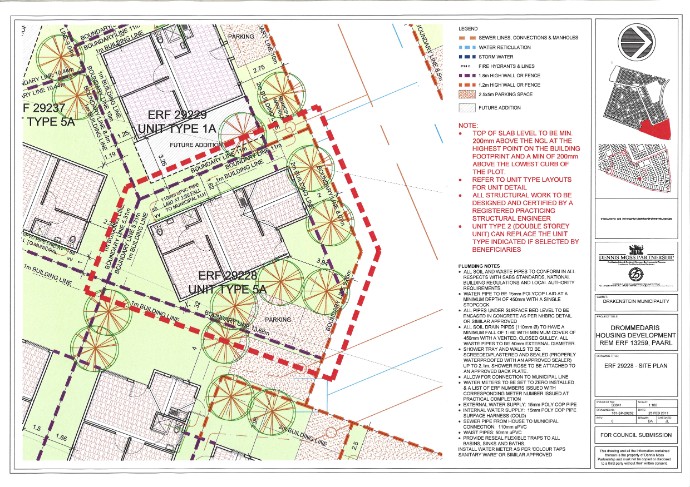
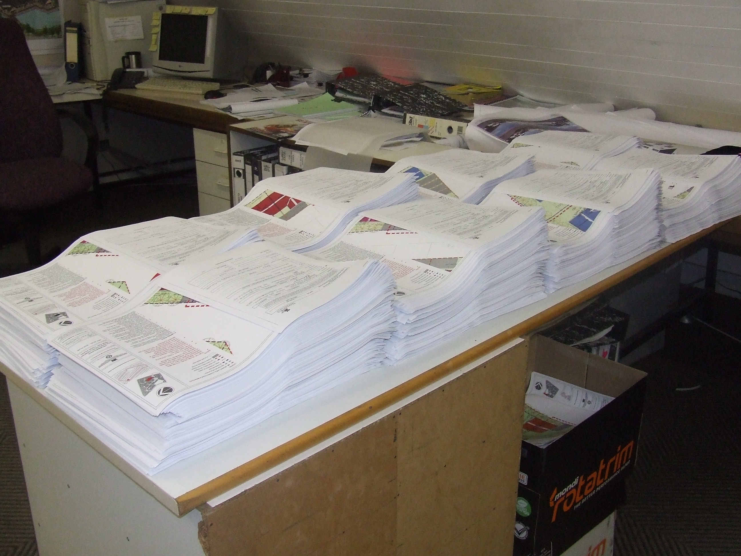
We had to submit these plans to the municipality so that it can be approved and so that construction could begin. This project was started in 2010 by another architect in the firm. When the project was handed down to us the unit type houses were already placed on the ERF's on AutoCAD so we had to and everything else that would be required for it to be submitted. In terms of my section I first had to put in the green hatch which represents the grass on the plots. I had to then title every single plot in terms of boundary and building lines, the dimensioning and the drainage connections. The ERF numbers had already been put on by a senior architect at the firm. I also had draw in the drainage pipe connections to the municiple manhole. After all this was down we had to put each individual ERF/plot on an A3 page so that it could be printed (The above picture in an example of my own of what it had to look like). I had to edit the title blocks of all the plots because the all the plots have different plot numbers. I have not put all the plots on because it is a lot of drawings and I thought it would take up a lot of space.

These are examples of the walls that would devide up the different plots. The proposed wall layout is represented by the purple and orange stippled lines. Purple being 1.8m and orange being 1.2m high walls. This drawing is a vibracrete wall proposal. I had to draw it up and put in the necessary titling.

The above was a proposed fence wall with diamand mesh fencing and gum poles. I had to edit the hights of these walls, the titling and the foundation as the previous drawing was not up to standard.

This was the next stage of the Drommedaris Project. It is a much larger piece (as one can see if you look at the top right of the drawing) of the project comprising of 1407 low cost sustainable houses constructed from block work. This was a project that was again split between me and Aubrey Langeveldt (50\50). The section that I was responsible for was the area within the black stippled lines.

The area was split into different phases because of it being such a big area it would be a very big drawing of AutoCAD and it would of taken much longer to complete it. There are a total of 24 phases starting with 1A, 1B, 2A, 2B.... all the way to 12B. An example of a phase is represented the the drawing above. Myself and Aubrey where responsible for the phases that fell under our respected areas.
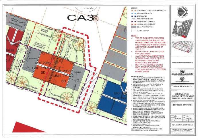
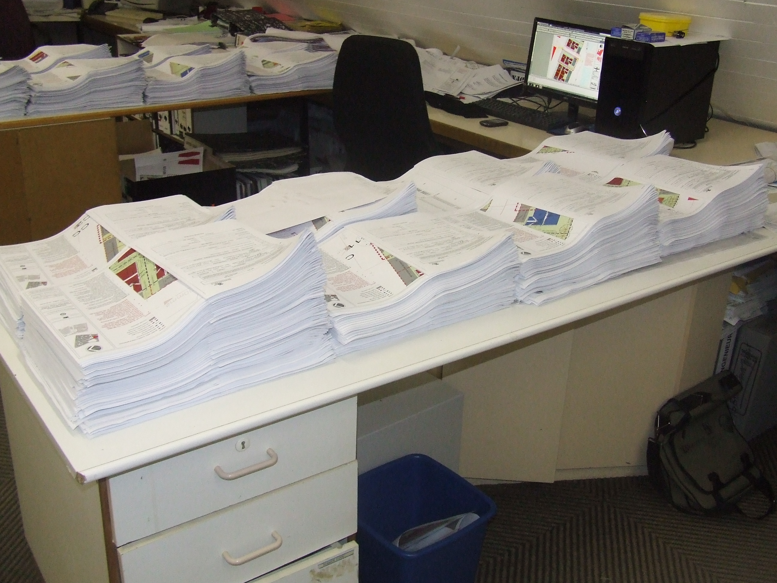
This is another example of what our end drawing had to look like for municiple submission. We had to do the same things in our respected sections as in the previous project (181 sustainable houseing project). We had to chage the hatching of the parking and the unit types though so that the text of the drawings would be much clearer .The only other difference was that we had to do this many, many more times. This is a project that took us the whole of march to complete working all day and every working day of the week. In this project the different unit types are represented by the different colours on the unit types on the plan. Making it clear to see which unit type is represented. In total there are four different unit types represented on the whole area of the site. The unit types are visible on the complete 1407 site plan. I have not put all the plots on because it is a lot of drawings and I thought it would take up a lot of space.
THE END RESULT
Q & A
1) What is the purpose of the drawing/information?
2) Who are the people for whom you have prepared the drawing/information?
3) Are there any other ways to provide the same drawing/information?
4) Explain the purpose of every component of the drawing/information mean (for example, why do you put certain dimensions on a specific drawing?)
1) The purpose of these drawing was to design houses that would fit onto a small erf as to maximise the number of units to be placed on the site. 2) These drawings are for Paarl municipality so that the drawings can be approved. It is also for the poorer community who are not able to afford and construct there own houses. 3) The drawings are also in PDF form for easier access and for referencing. 4) On these drawings all the dimensions on all the ERFs are there so that the contractor is able to construct the house. The boundary line units are given to show council and the contractor what his limits are in terms of the construction. The dashed lines indacates the fences on each drawing with different colours meaning different heights. The semi-detached units are represented by SD, and single unit types show there unit type number with the letters A or B next to the number. The legend helps one to understand the drawing better. The drainage pipes and municiple connections are shown so that it is clear where the pipes lie.
This free website was made using Yola.
No HTML skills required. Build your website in minutes.
Go to www.yola.com and sign up today!
Make a free website with Yola