DROMMEDARIS
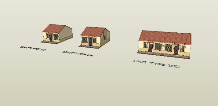
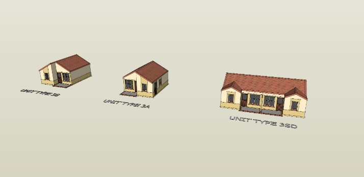
These are the units that where used in the previous project I posted called Drommerdaris. From the drawings we plotted myself and Aubrey Langeveldt had to create sketch up models for prsentational purposes. The two pictures above are of the models I created, there are four unit types in total.
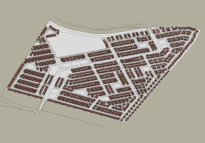
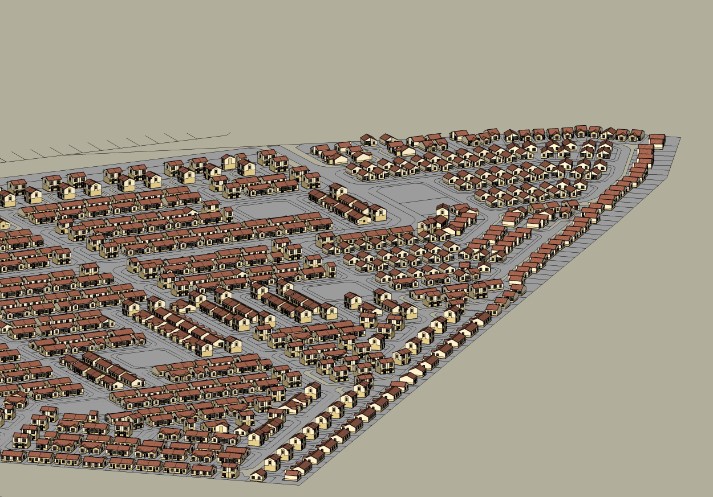
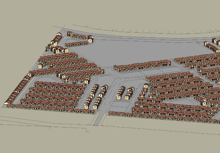
After these unit types were completed I had to place them on there respected ERFs in a sketch up model to create a model of the entire Drommerdaris project.
BLUE DOWNS NUWE BEGIN
Low cost housing project
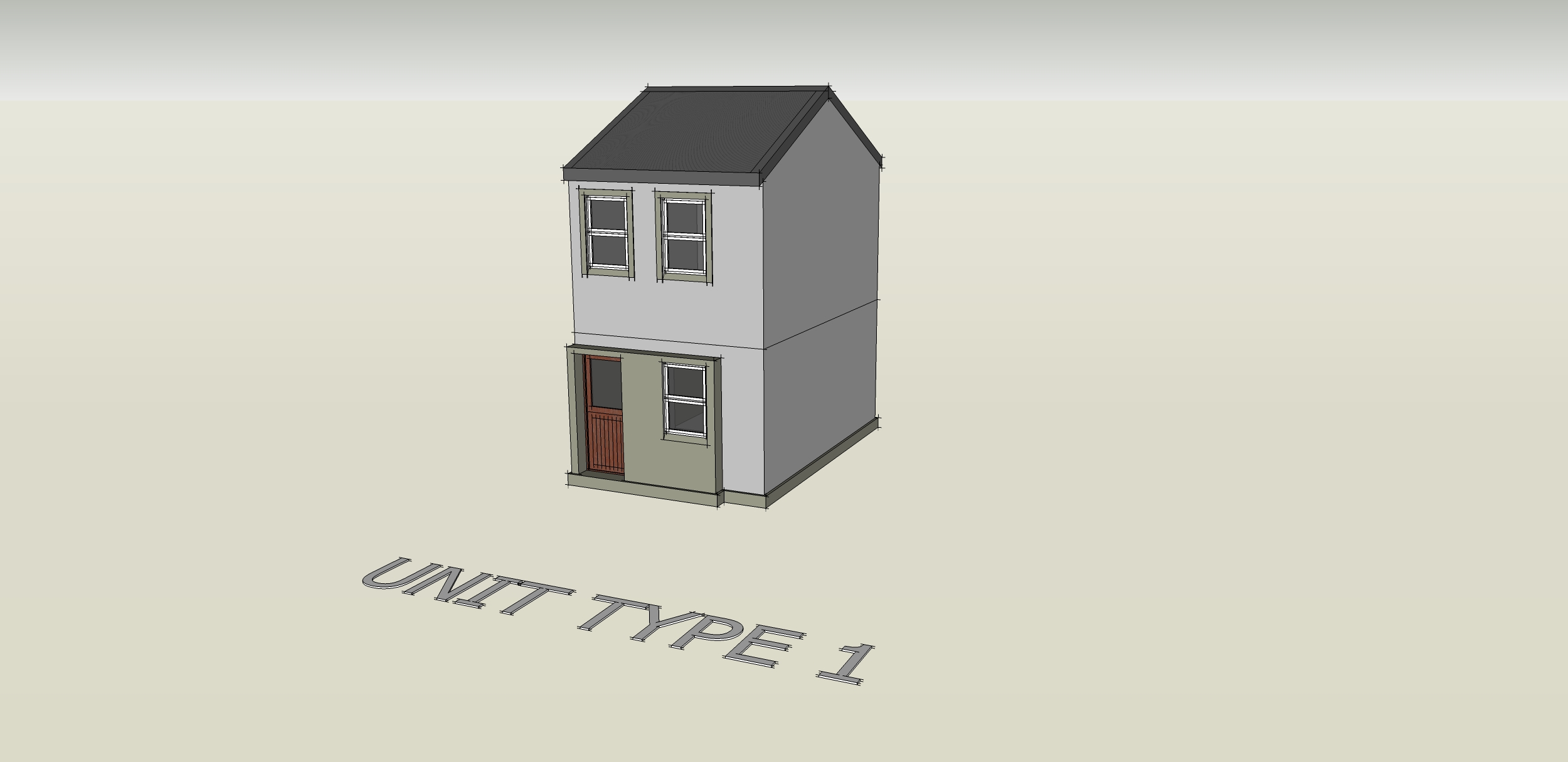
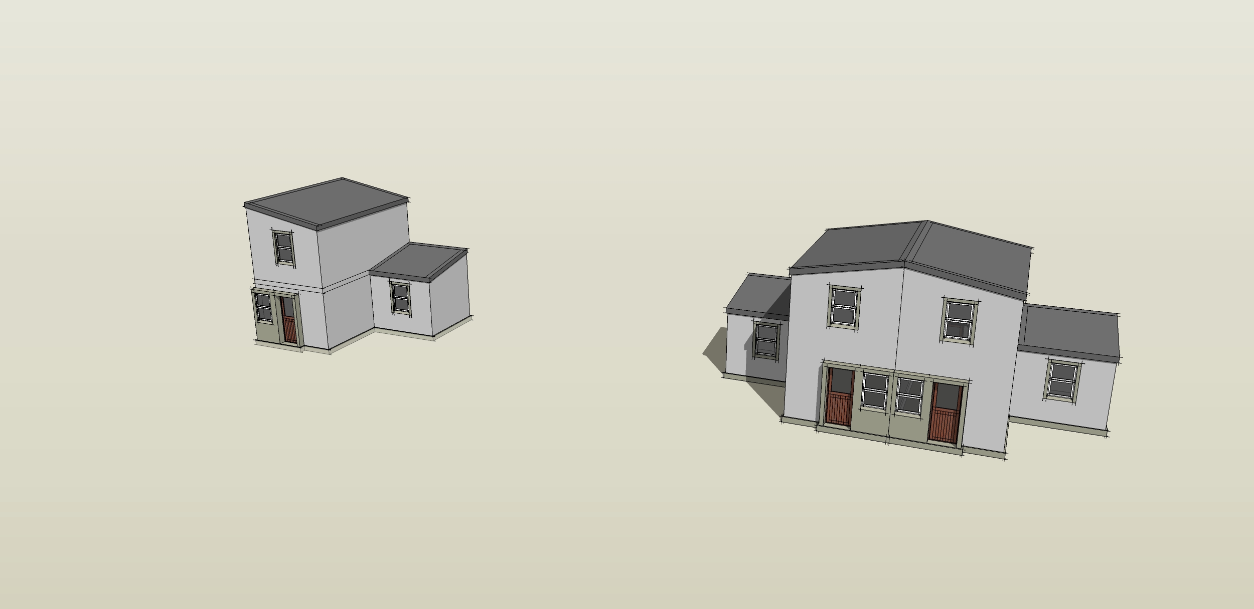
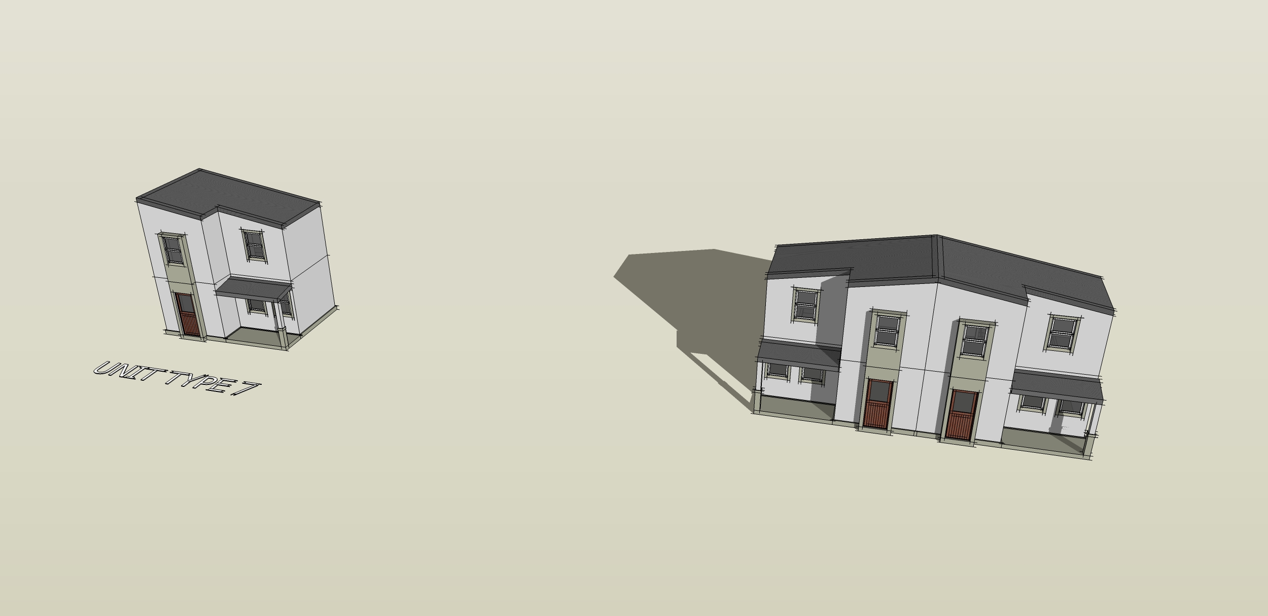
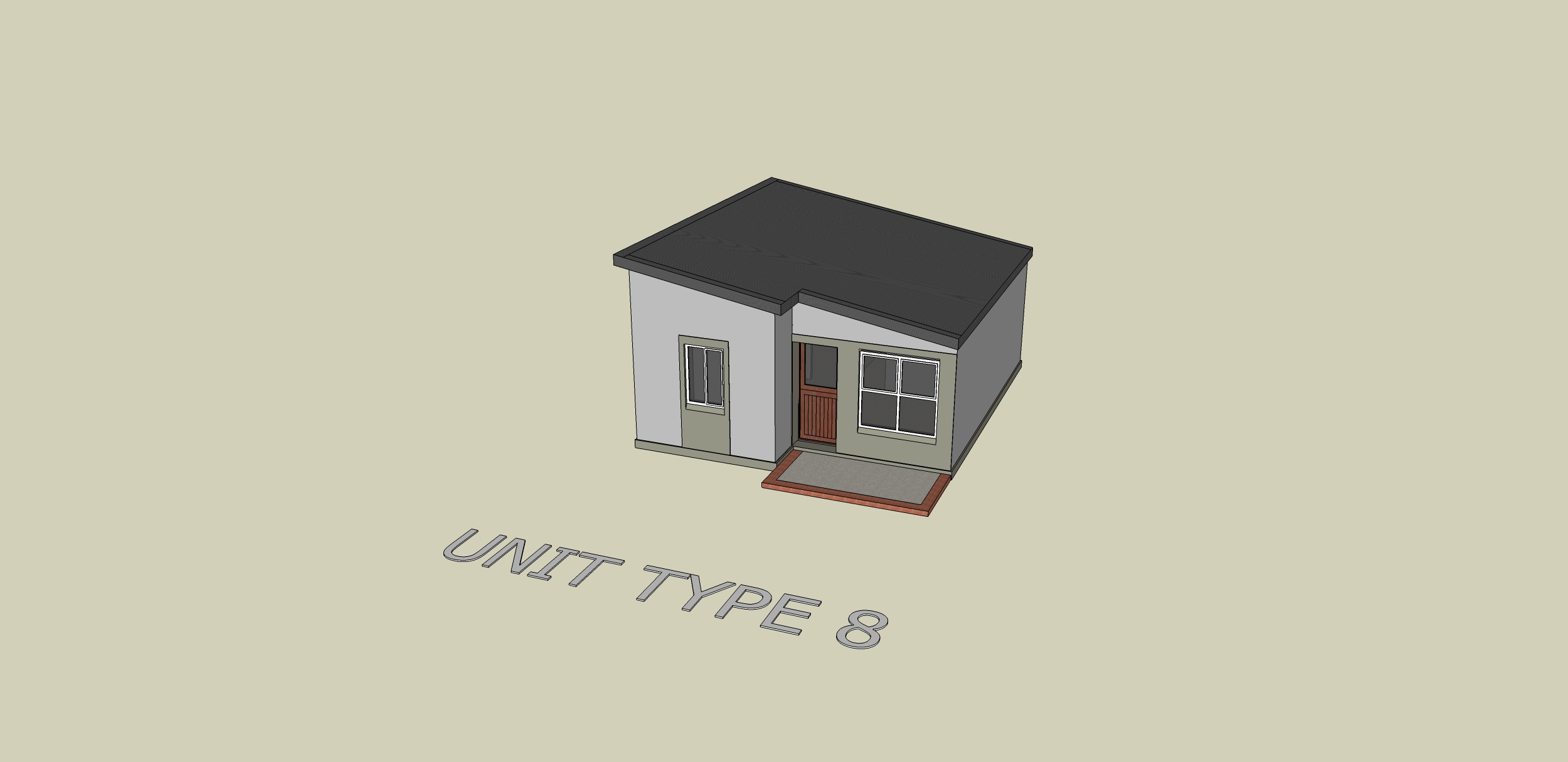
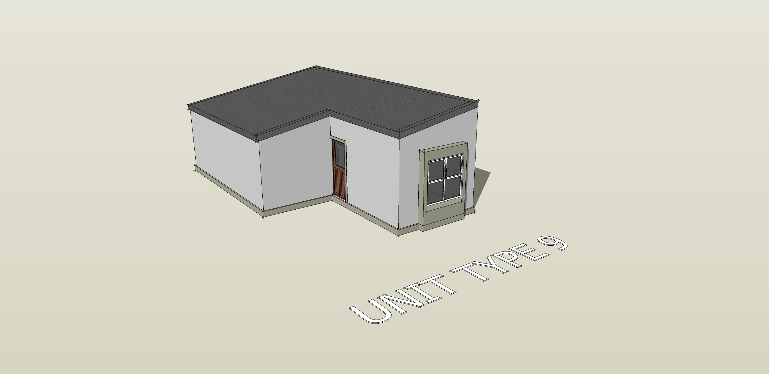
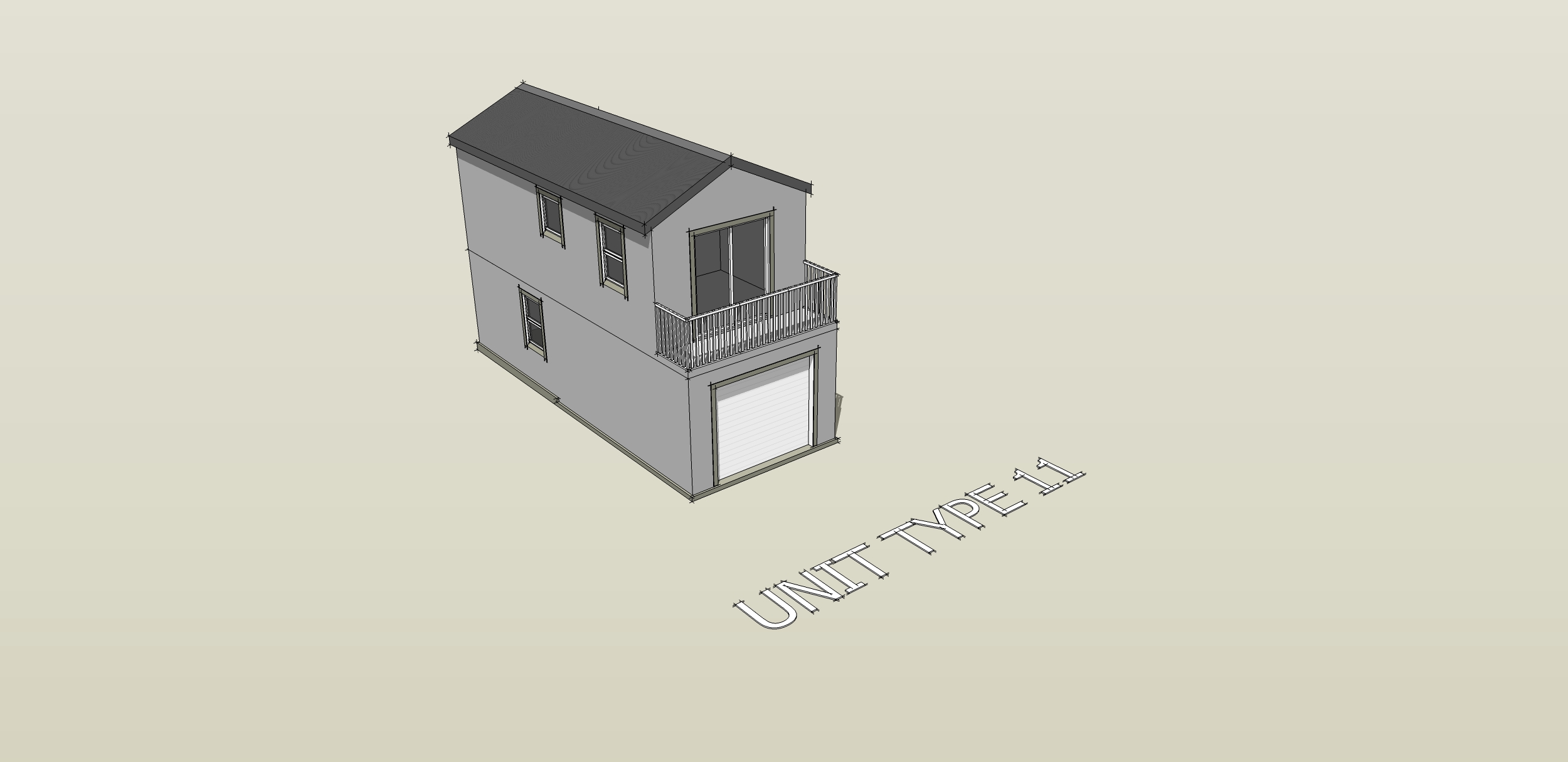
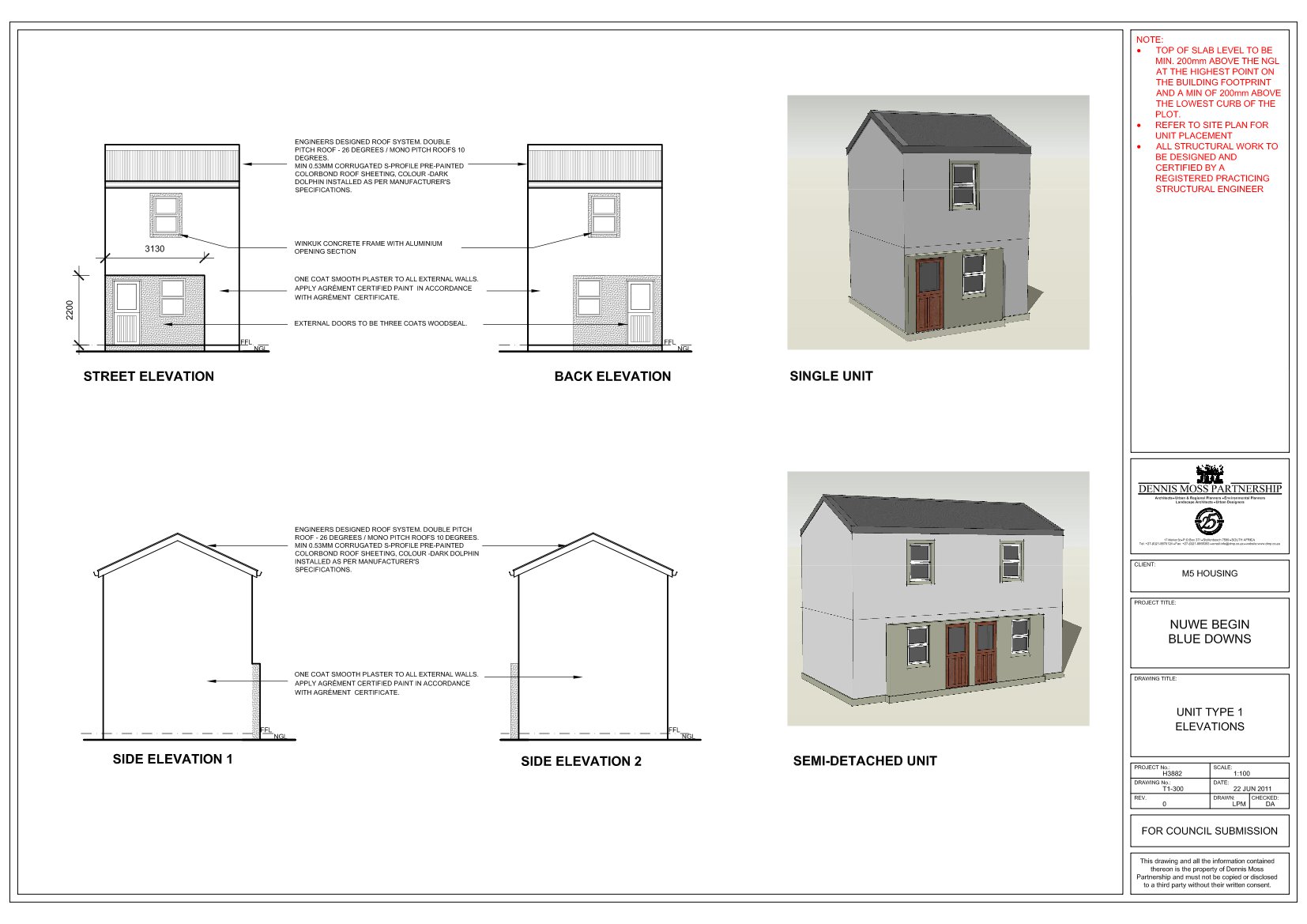
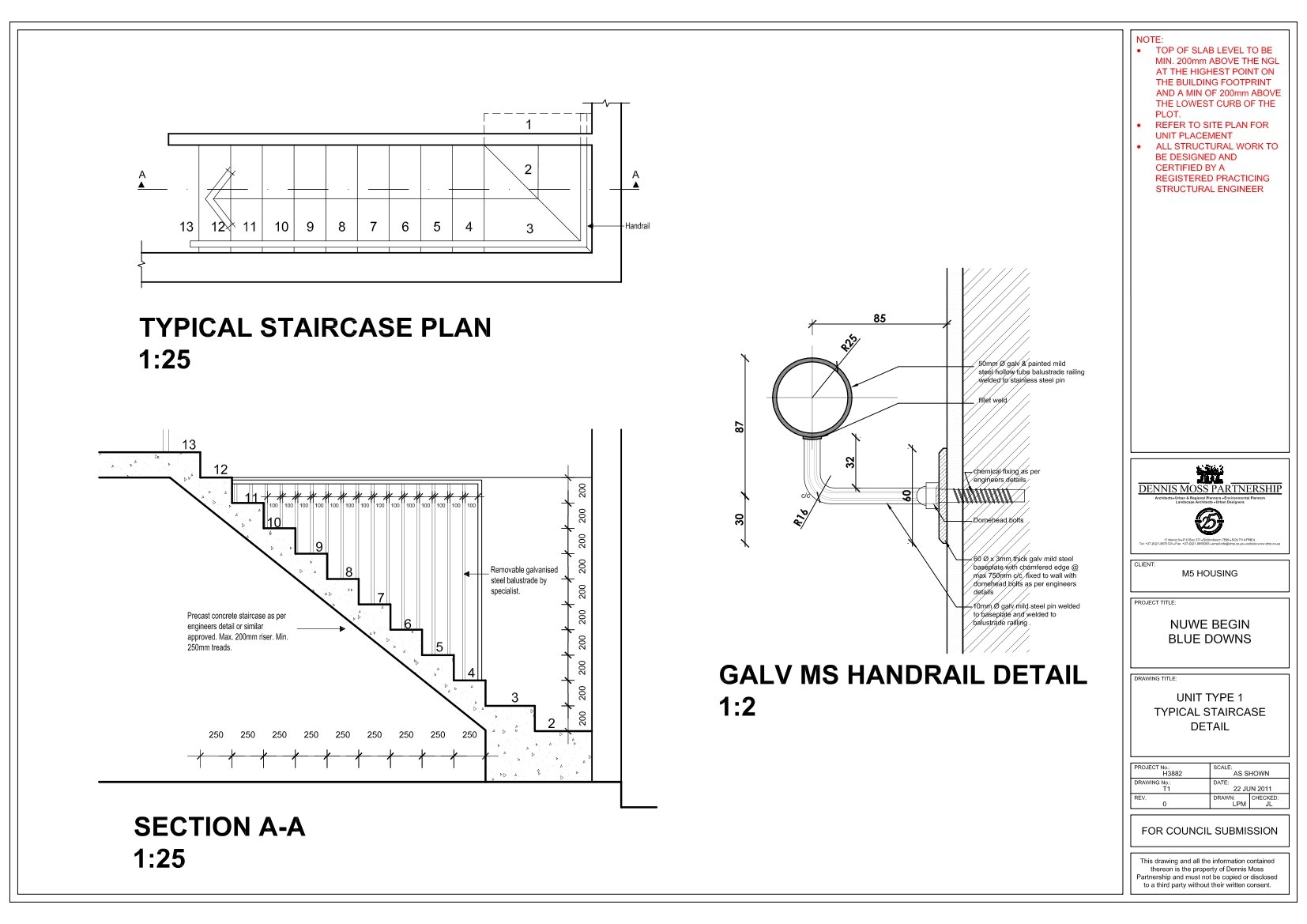
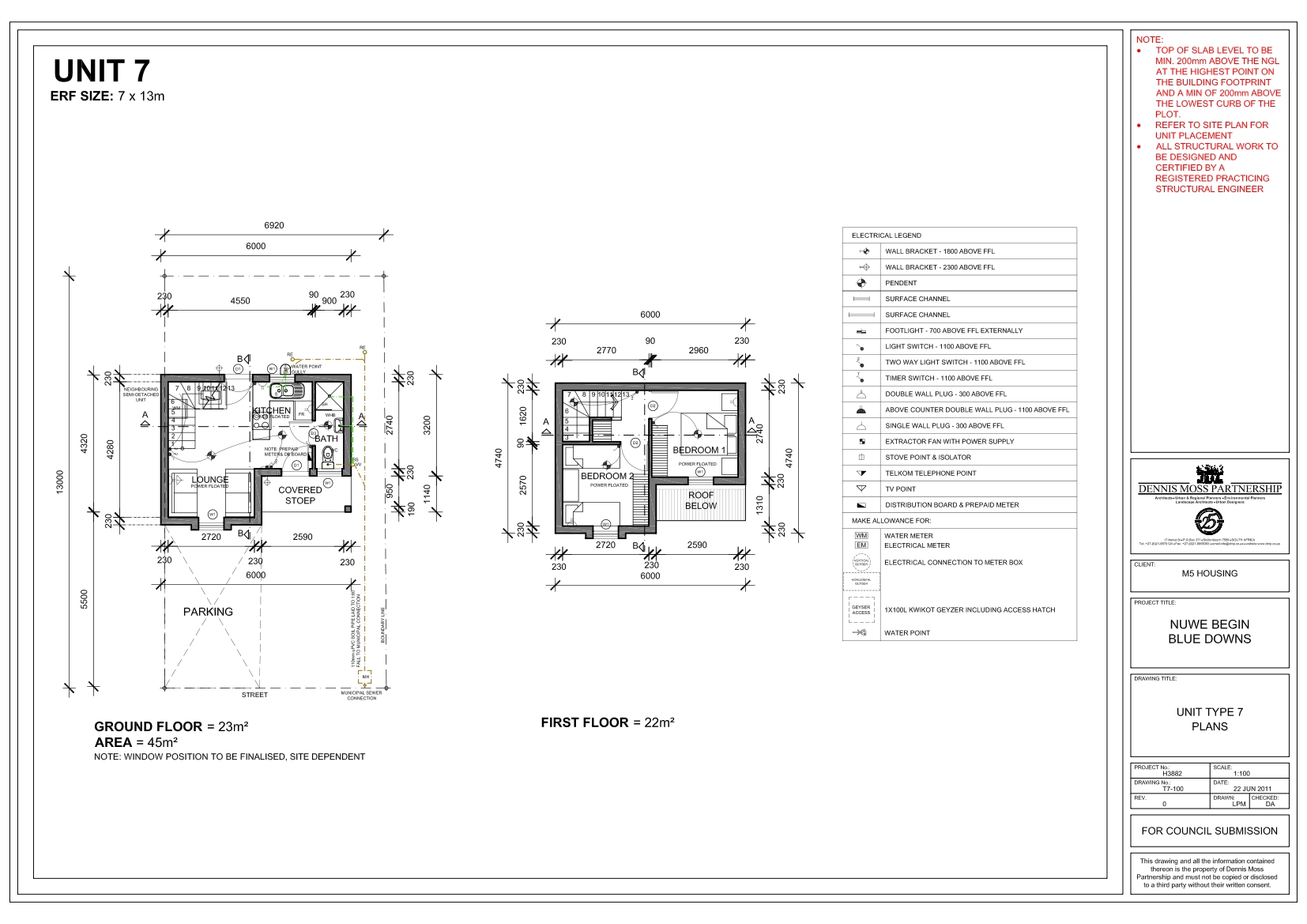
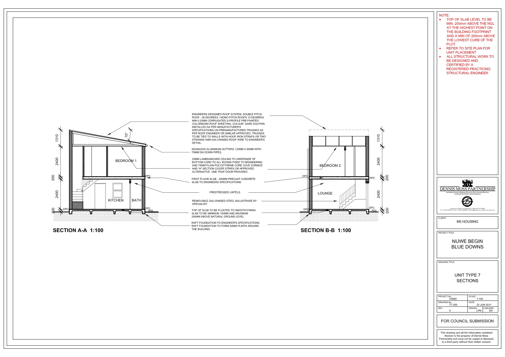
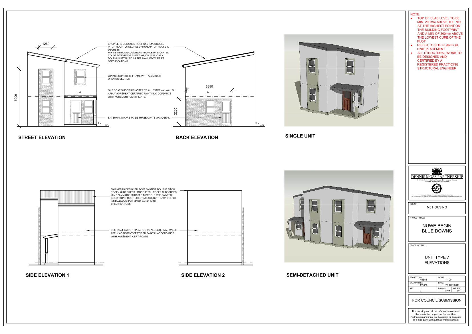
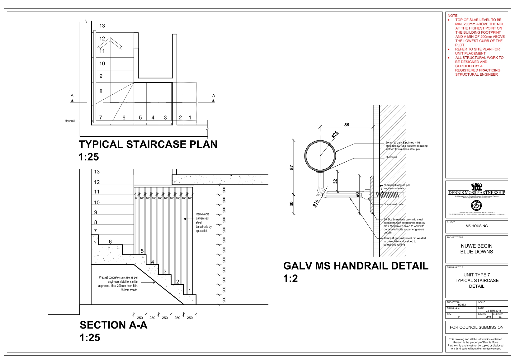
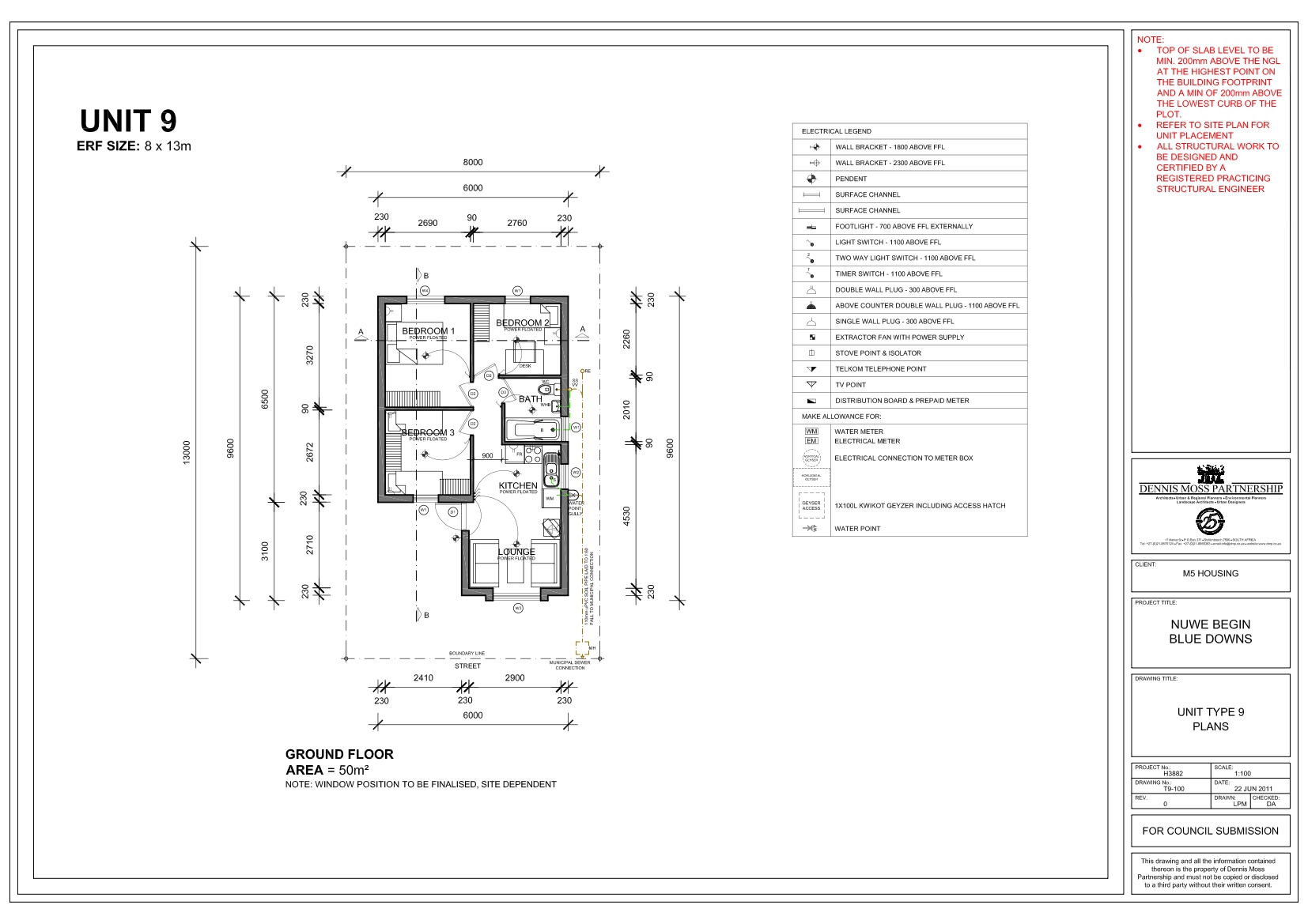
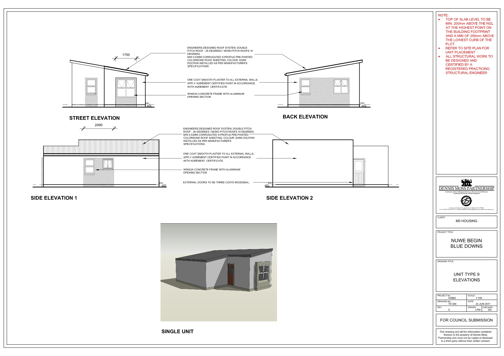
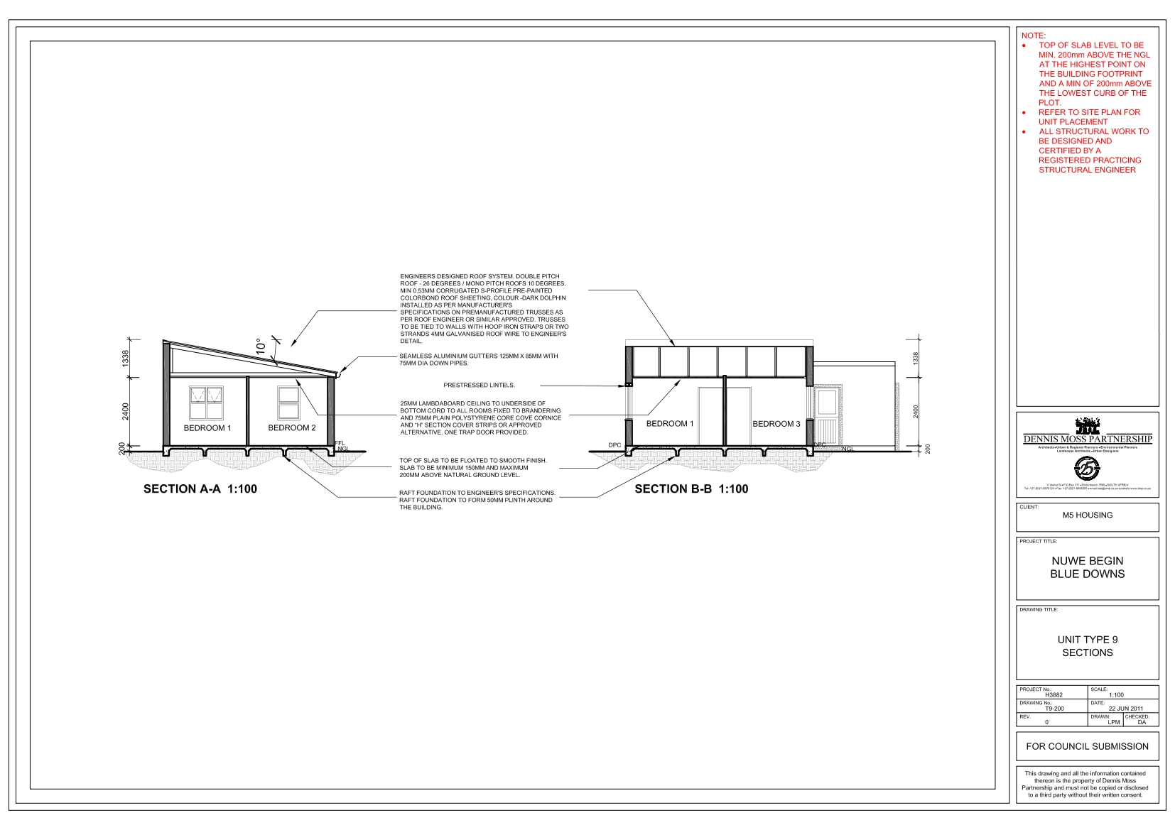
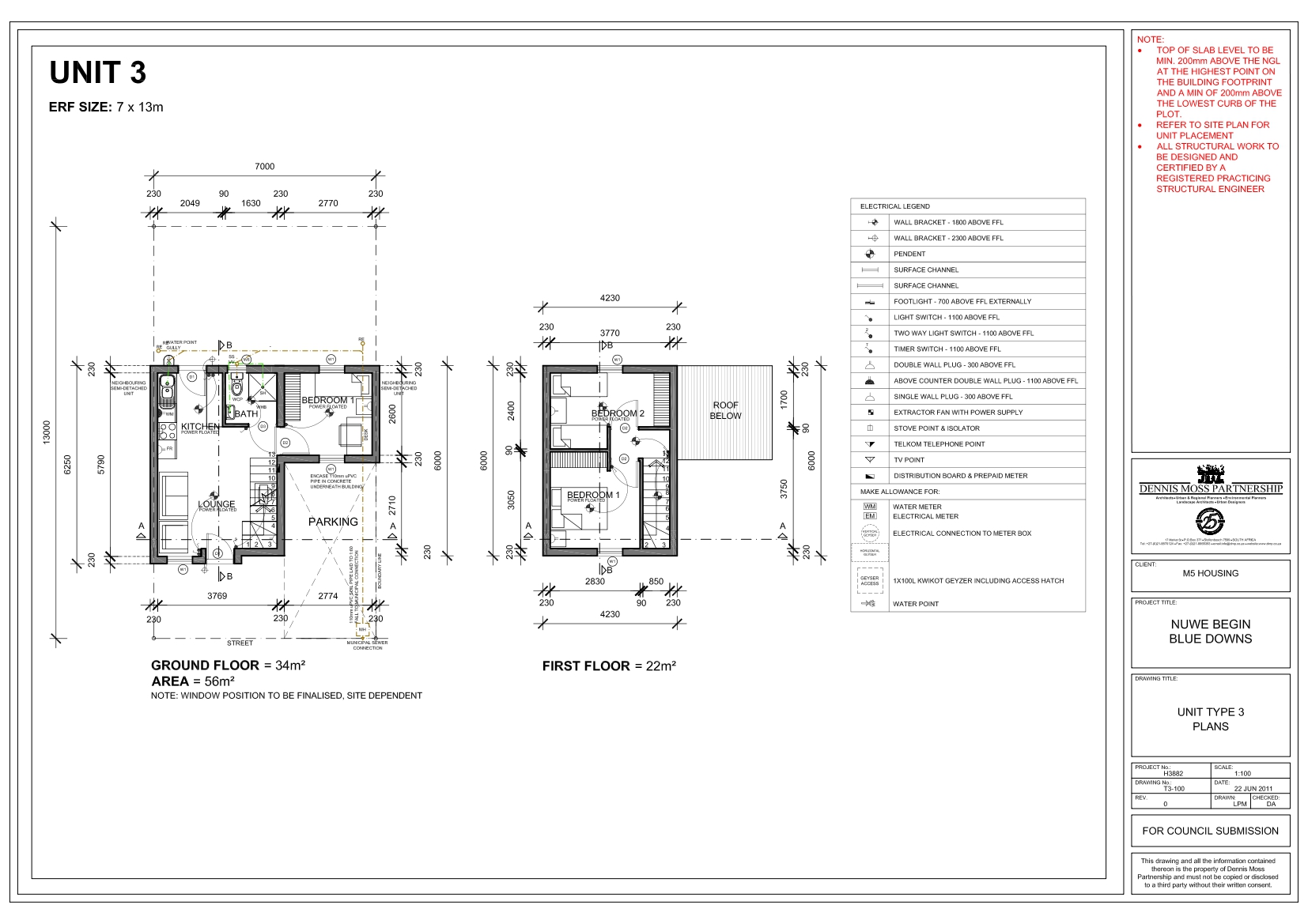
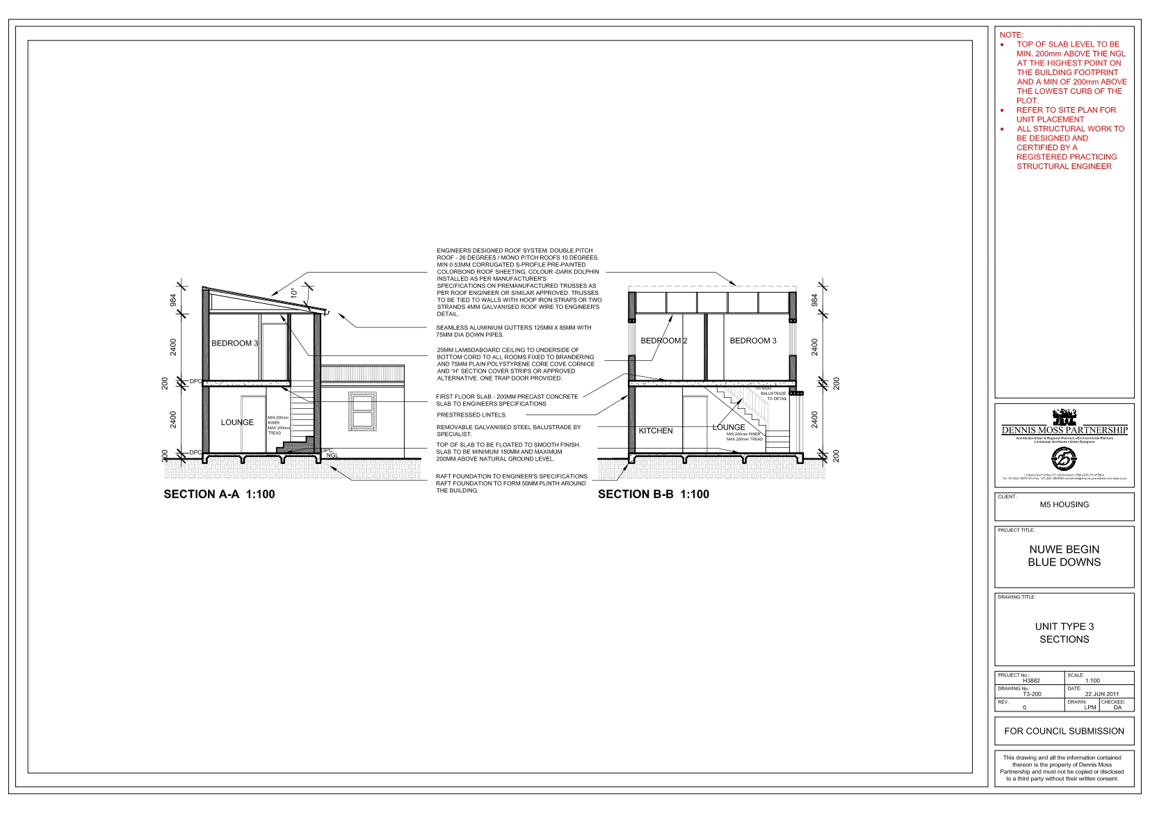
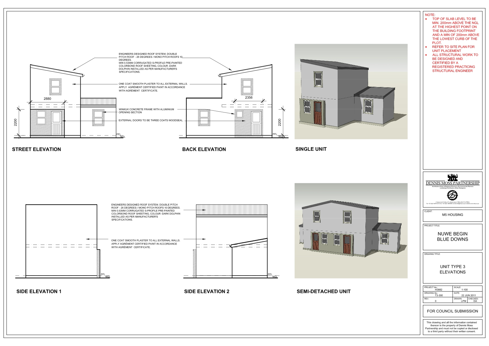
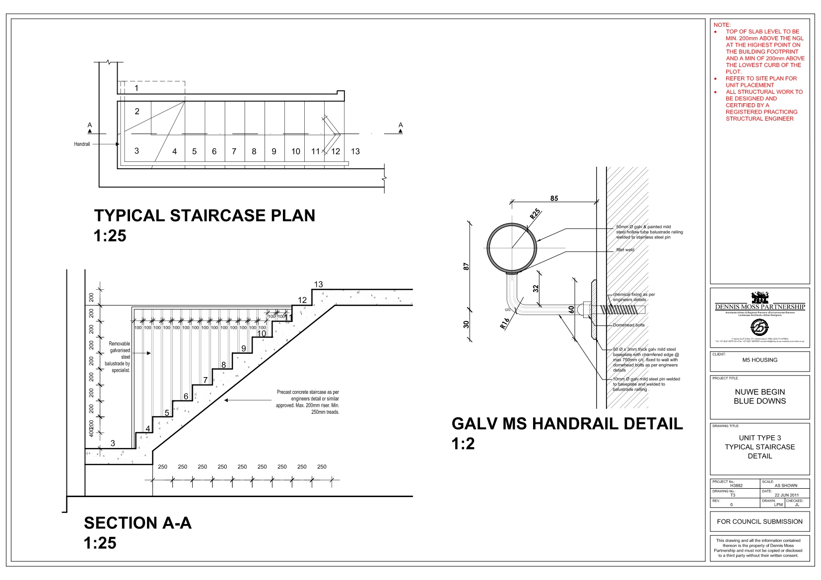
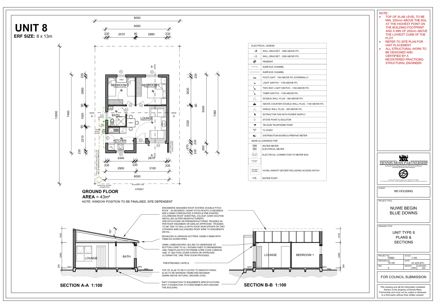
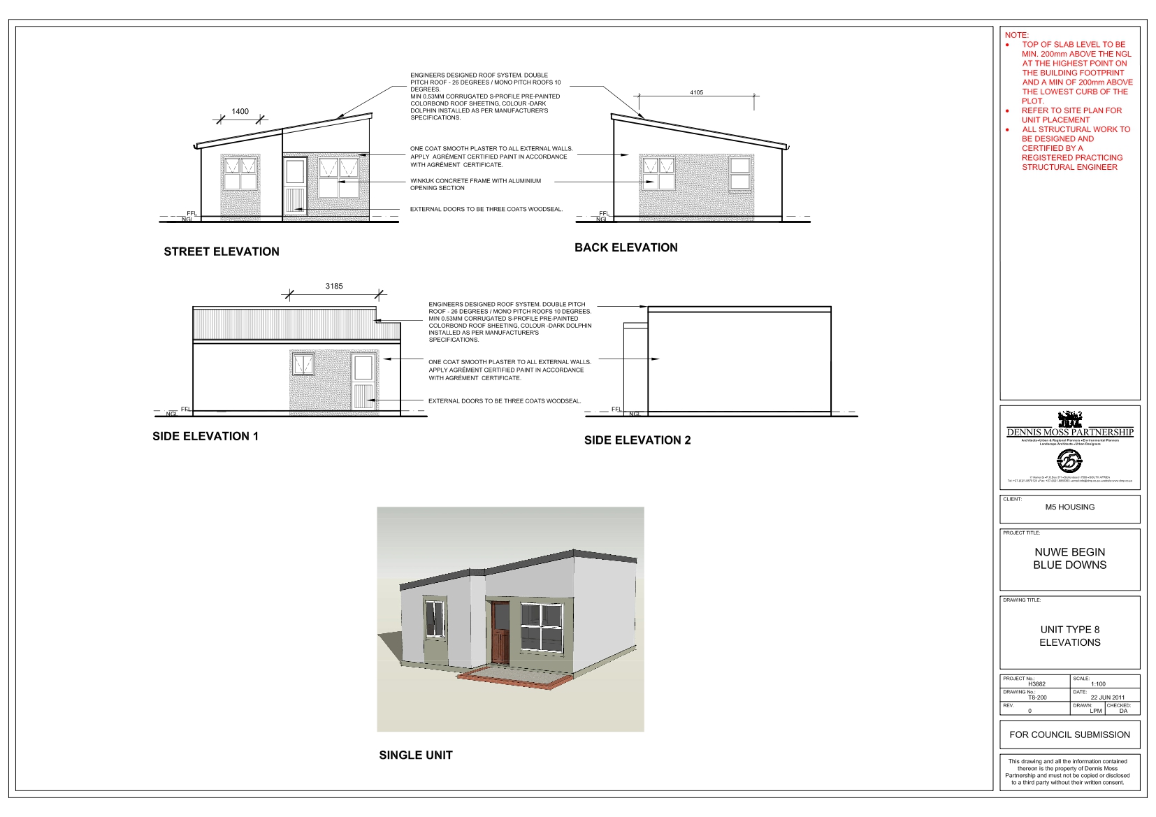
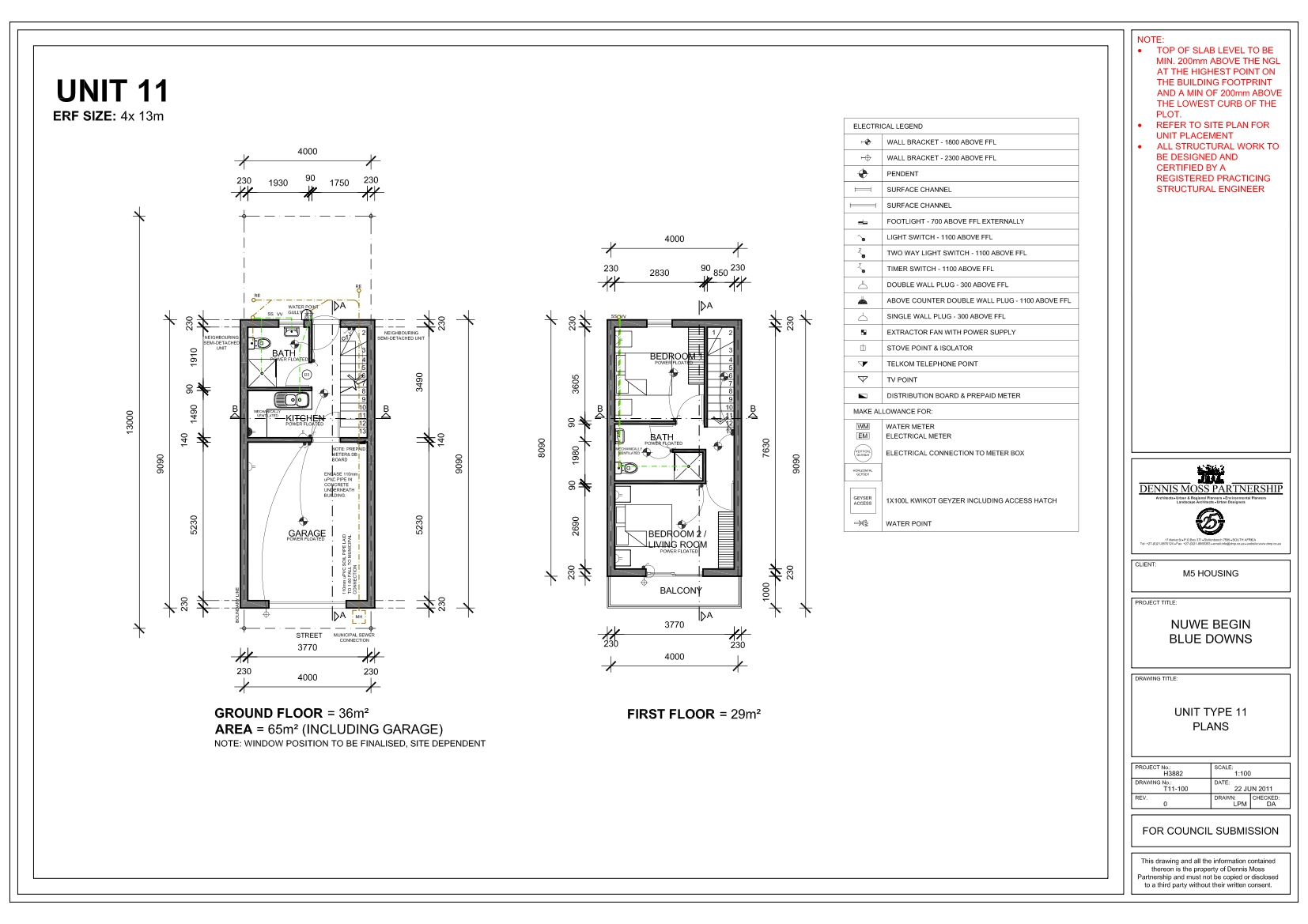
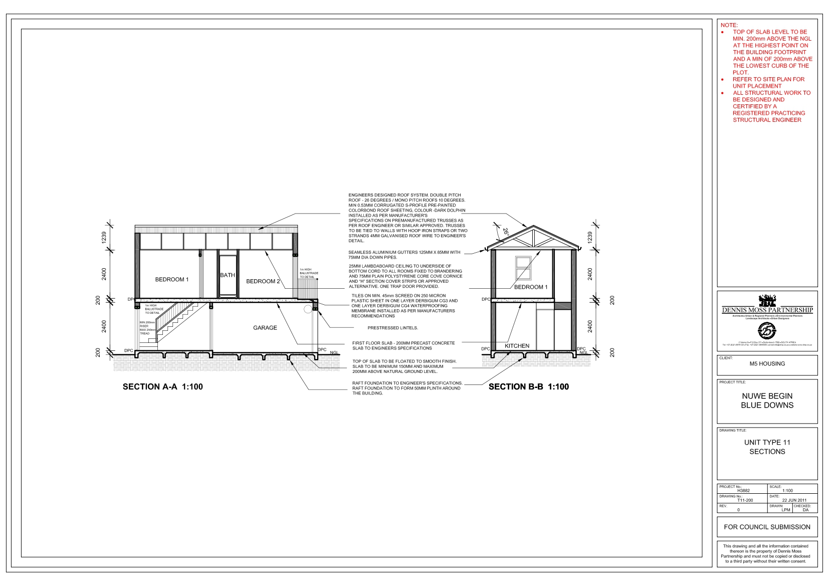
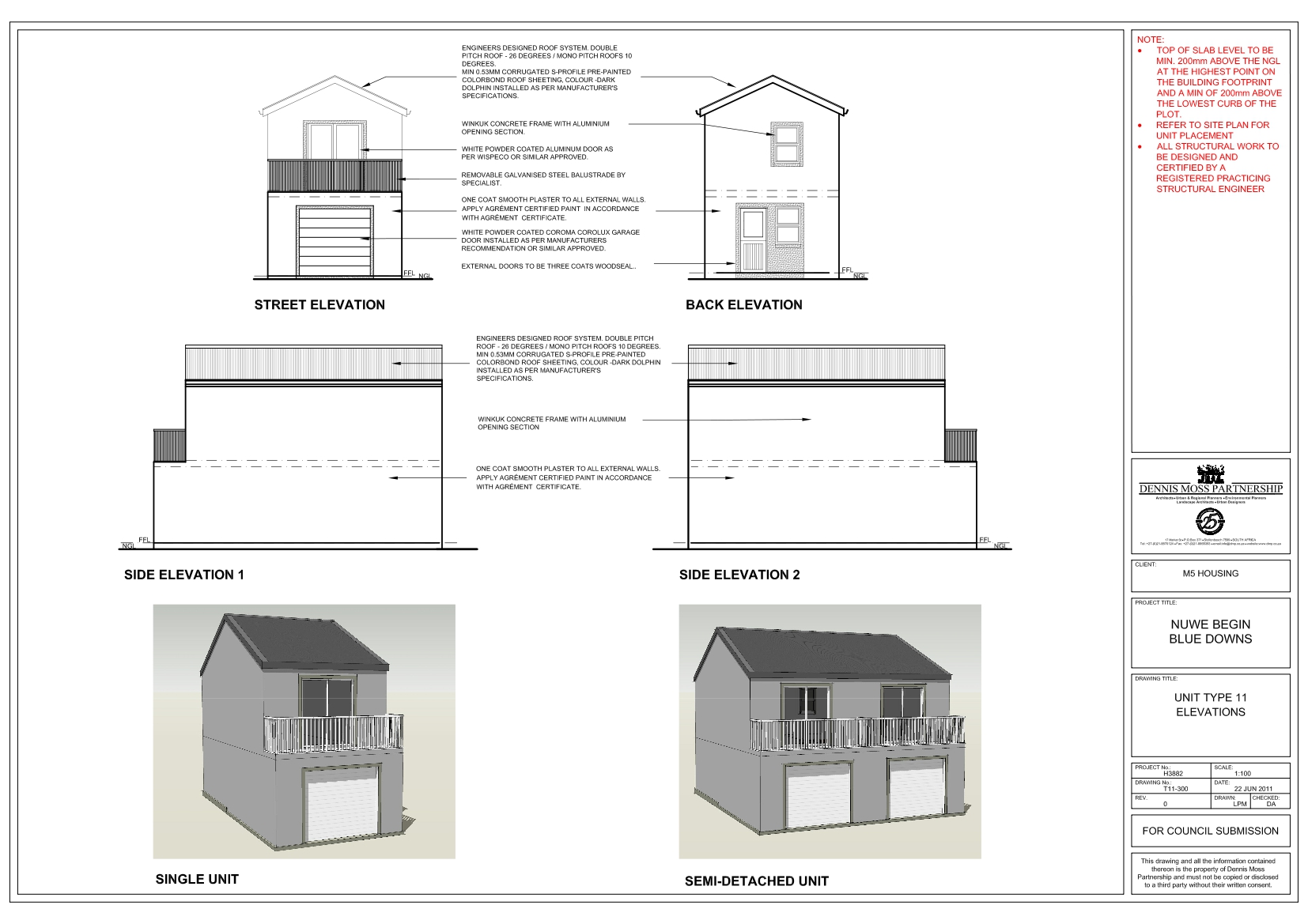
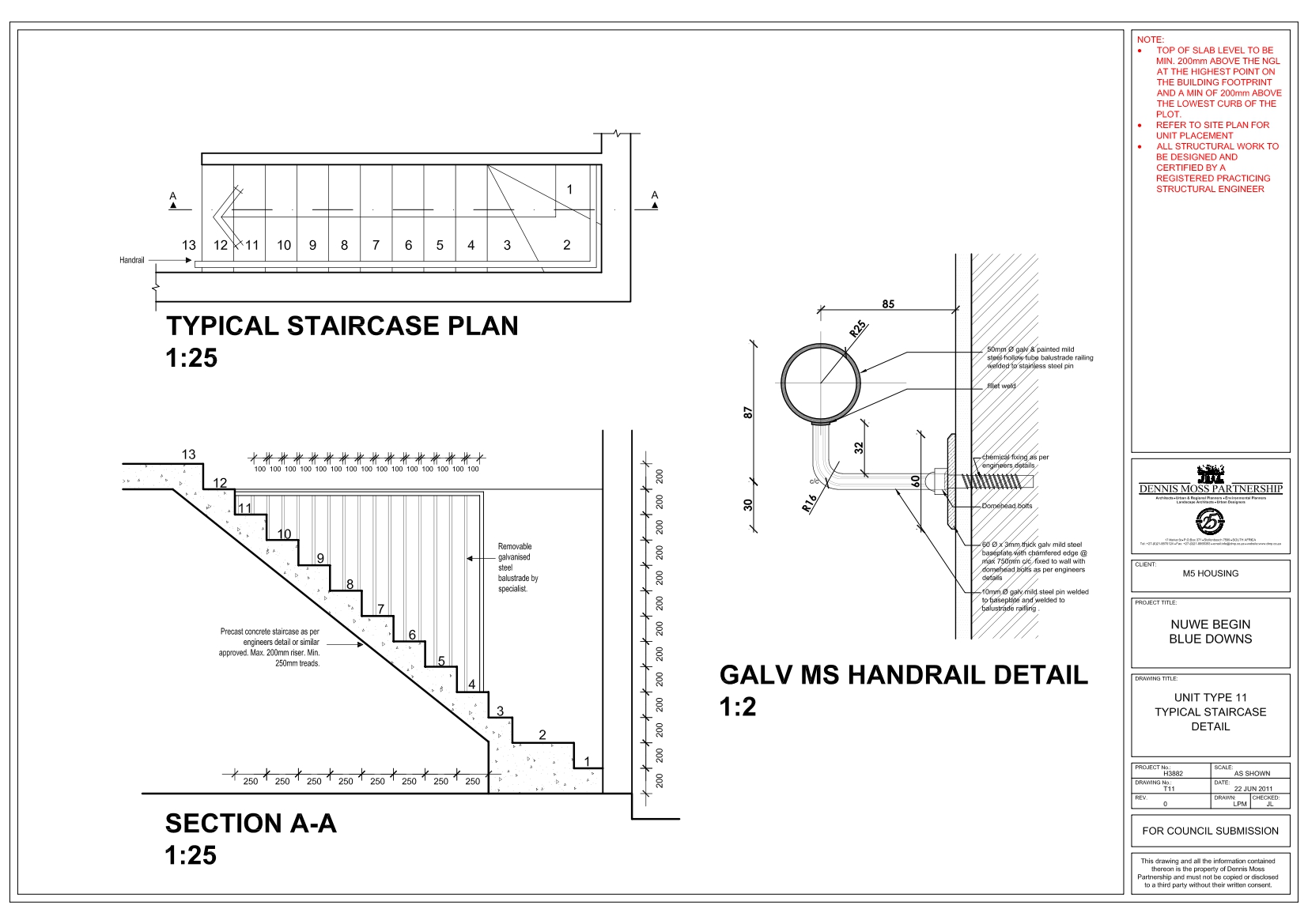
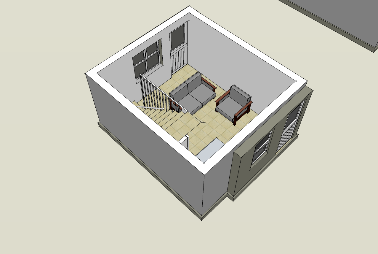
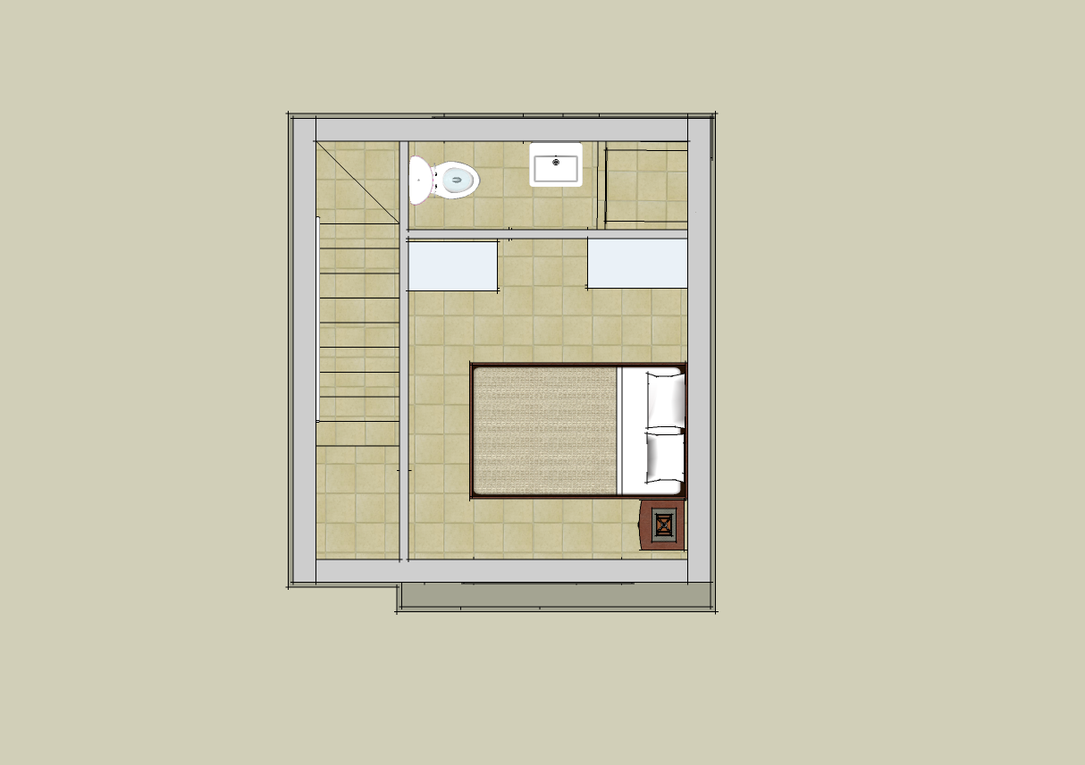
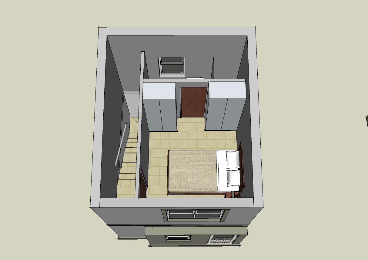
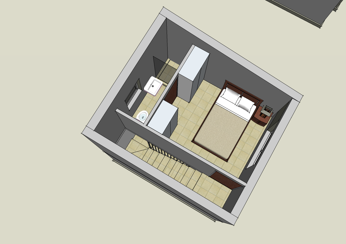
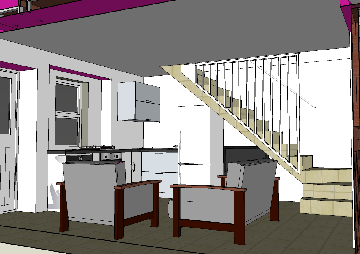
The above pictures are that of Sketch Up models which I had to create in relation to the unit types represented in PDF form below. The 'T' in the names of the PDFs refers to type/unit type the file represents and the number represents the option type. PDFs T-1,T-3, T-7, T-8, T9 and T-11 are Plans, Sections, Elevations and Specifications of the unit types. The others are to be used in booklets to show the respected clients.
UNIT TYPE 1 UNIT TYPE 7 UNIT TYPE 9 | UNIT TYPE 3 UNIT TYPE 8 UNIT TYPE 11 |
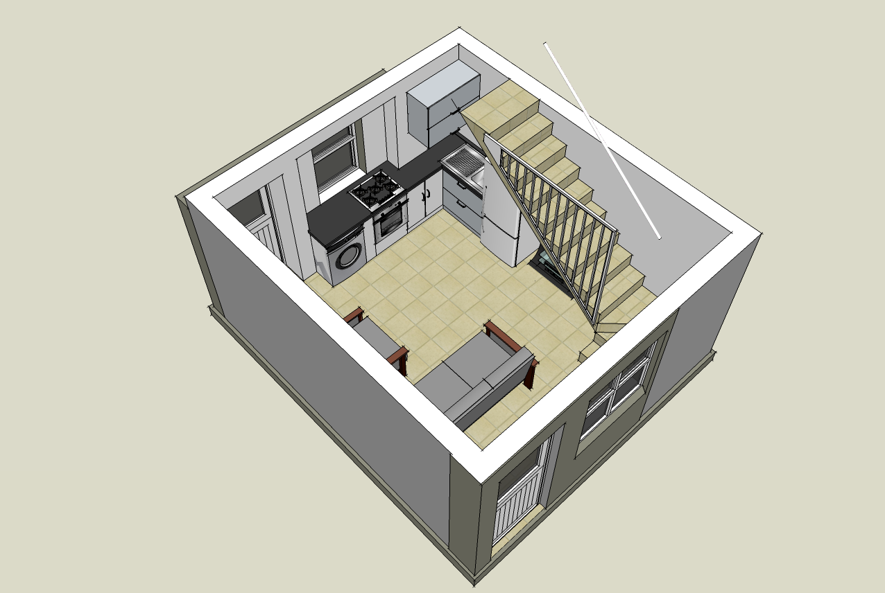
The above is one example of the fully furnished unit. This was done for all the above units.
Q & A
1) What is the purpose of the drawing/information?
2) Who are the people for whom you have prepared the drawing/information?
3) Are there any other ways to provide the same drawing/information?
4) Explain the purpose of every component of the drawing/information mean (for example, why do you put certain dimensions on a specific drawing?)
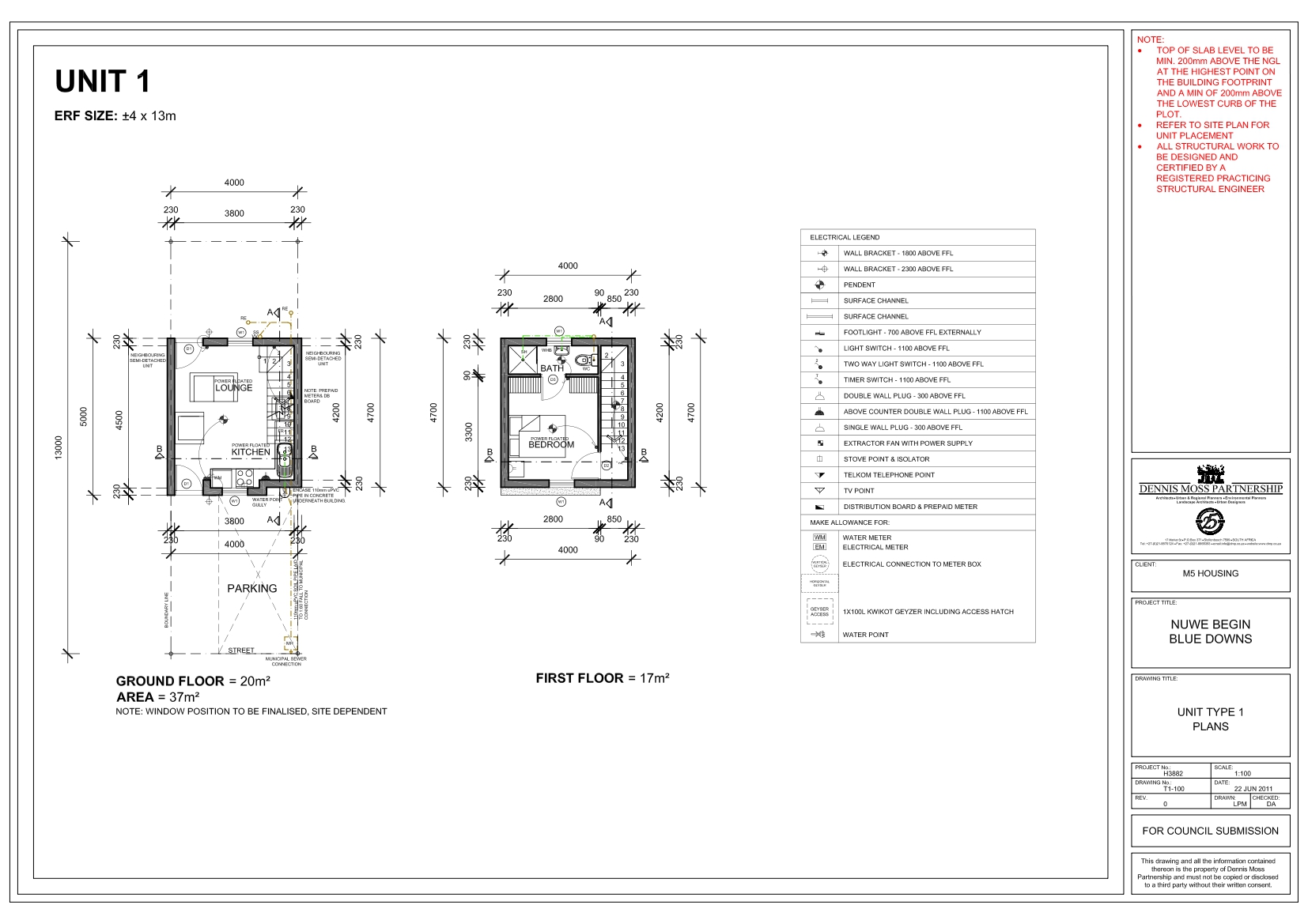
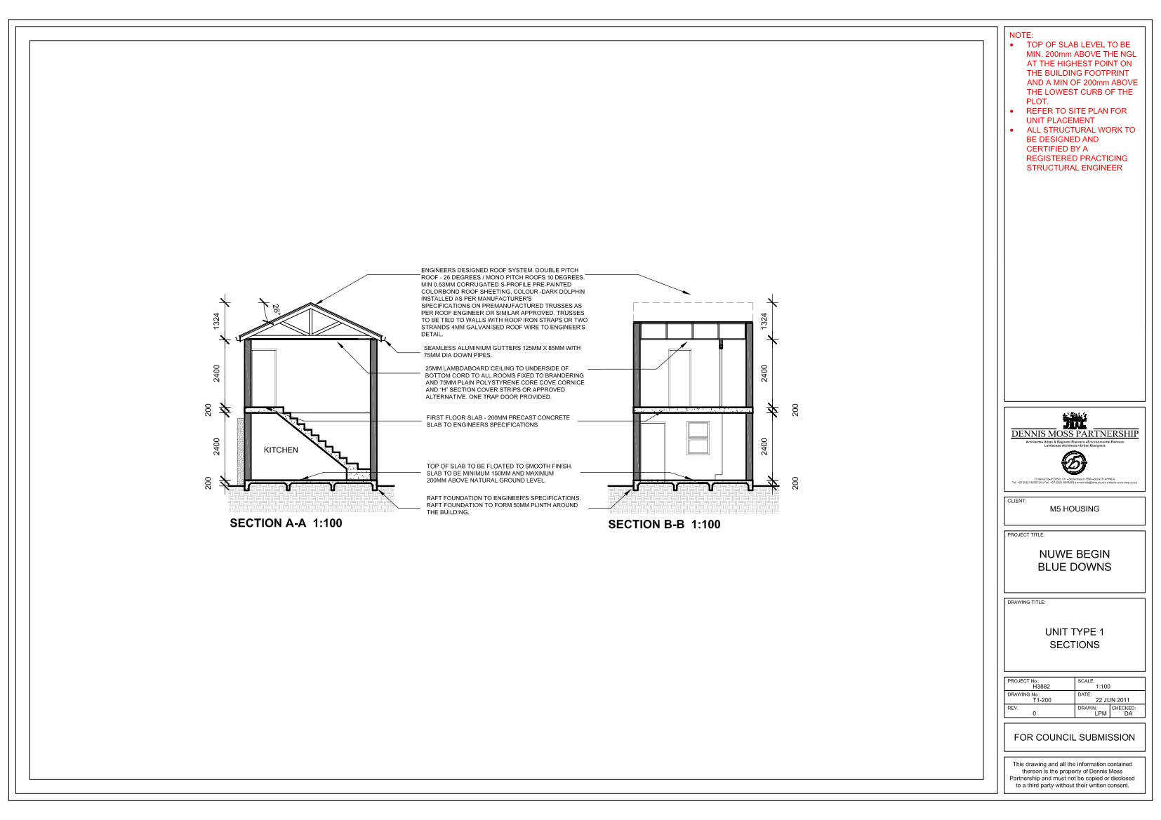
1) The purpose of the drawings was to create unit types within small erf size to maximise the quantity of houses. 2) These drawings are for the provicial government which the Blue Downs area falls under. Once it is approved it would be for the less fortunate who can not afford the luxury of buying there own home. 3) No 4) There has to be the correct amount of dimensions on each drawing so that the constractor is able to build from the plans. The sketch up models are for presentational purposes to show the client an indication of the finished product. There is an electrical layout to show where to plug pionts are. The appliances and furniture are an example of how the rooms can be layed out and also gives an indication of which room it is.FRANSCHOEK RETAIL DEVELOPMENT
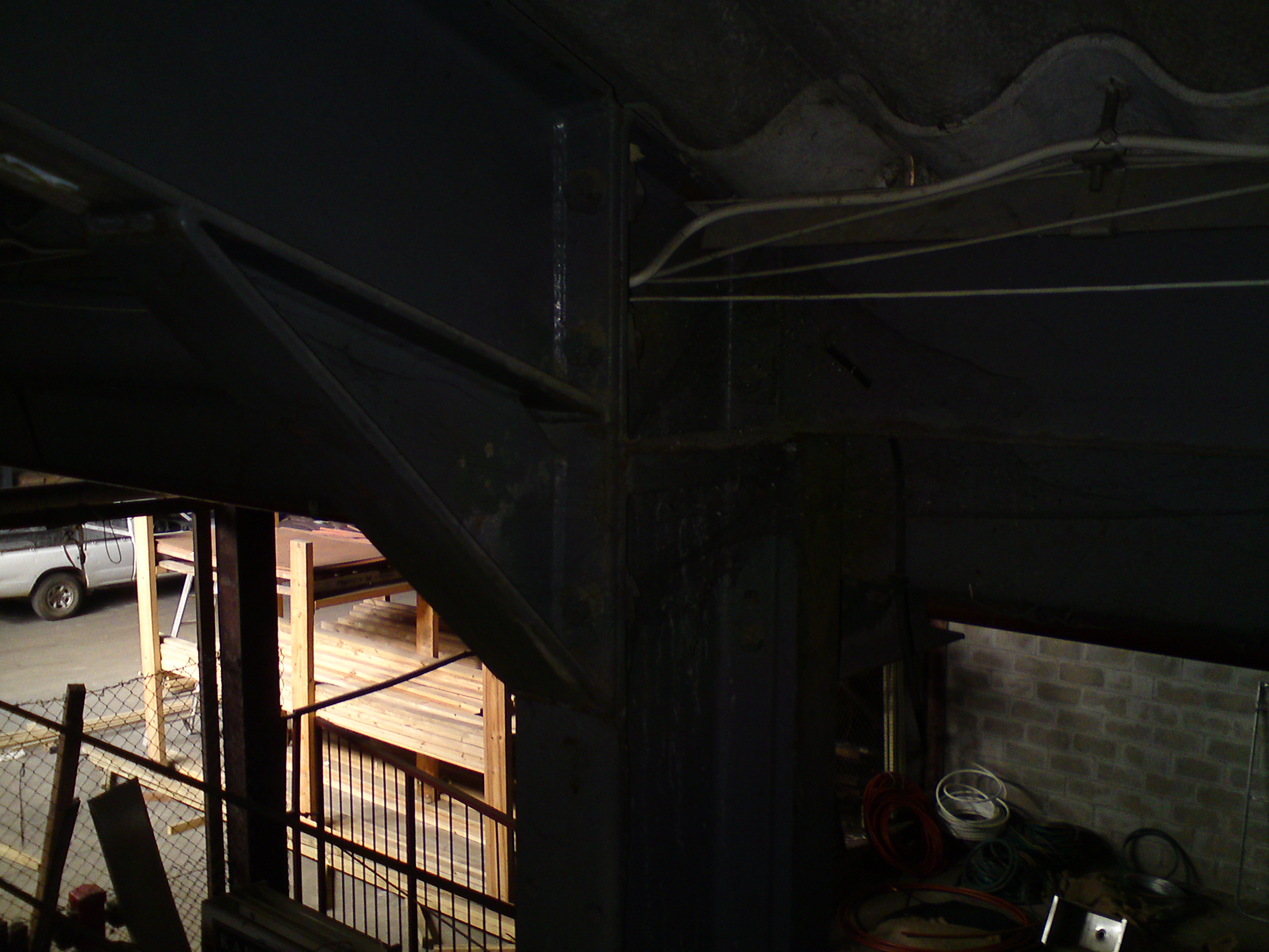
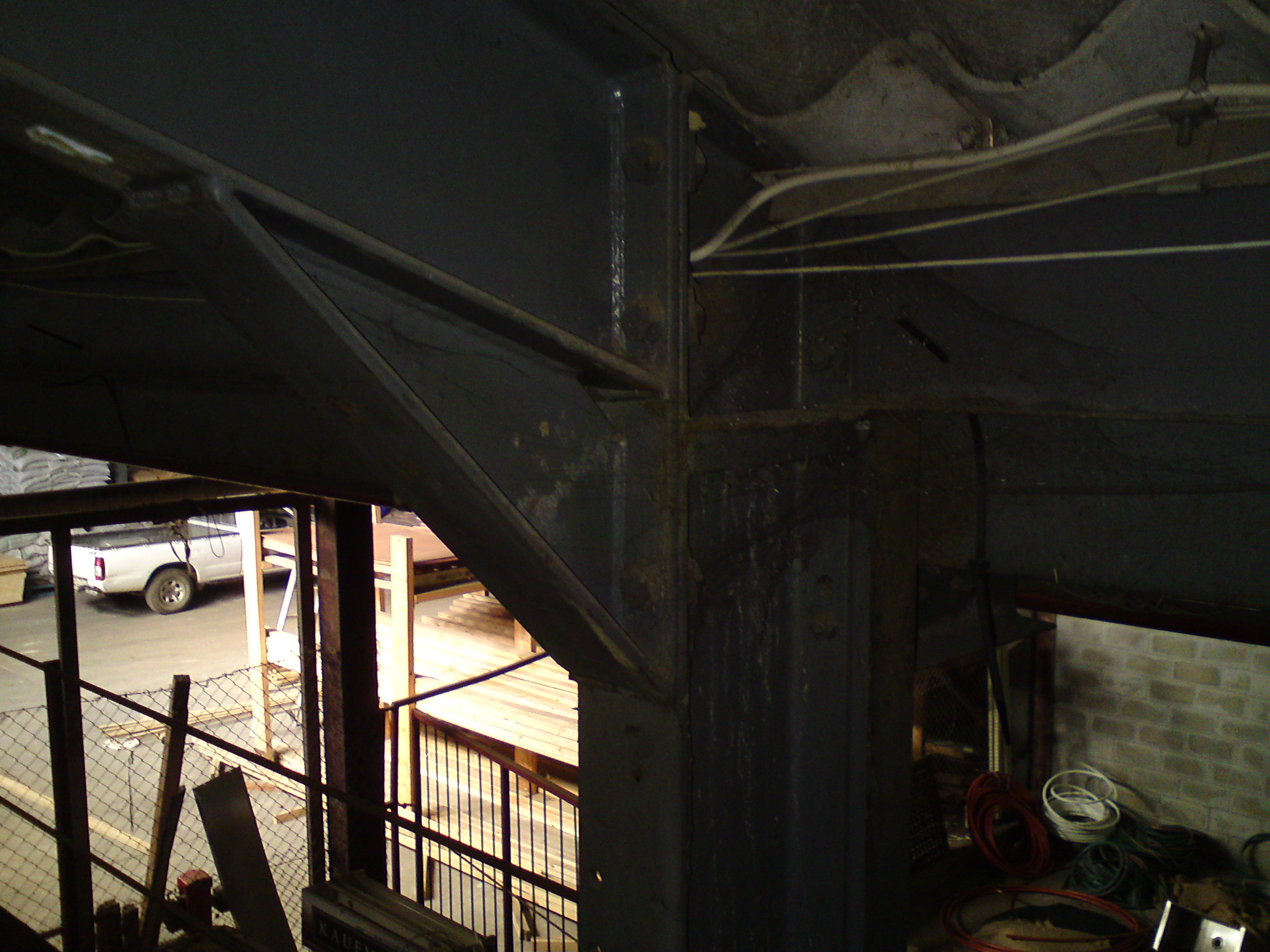
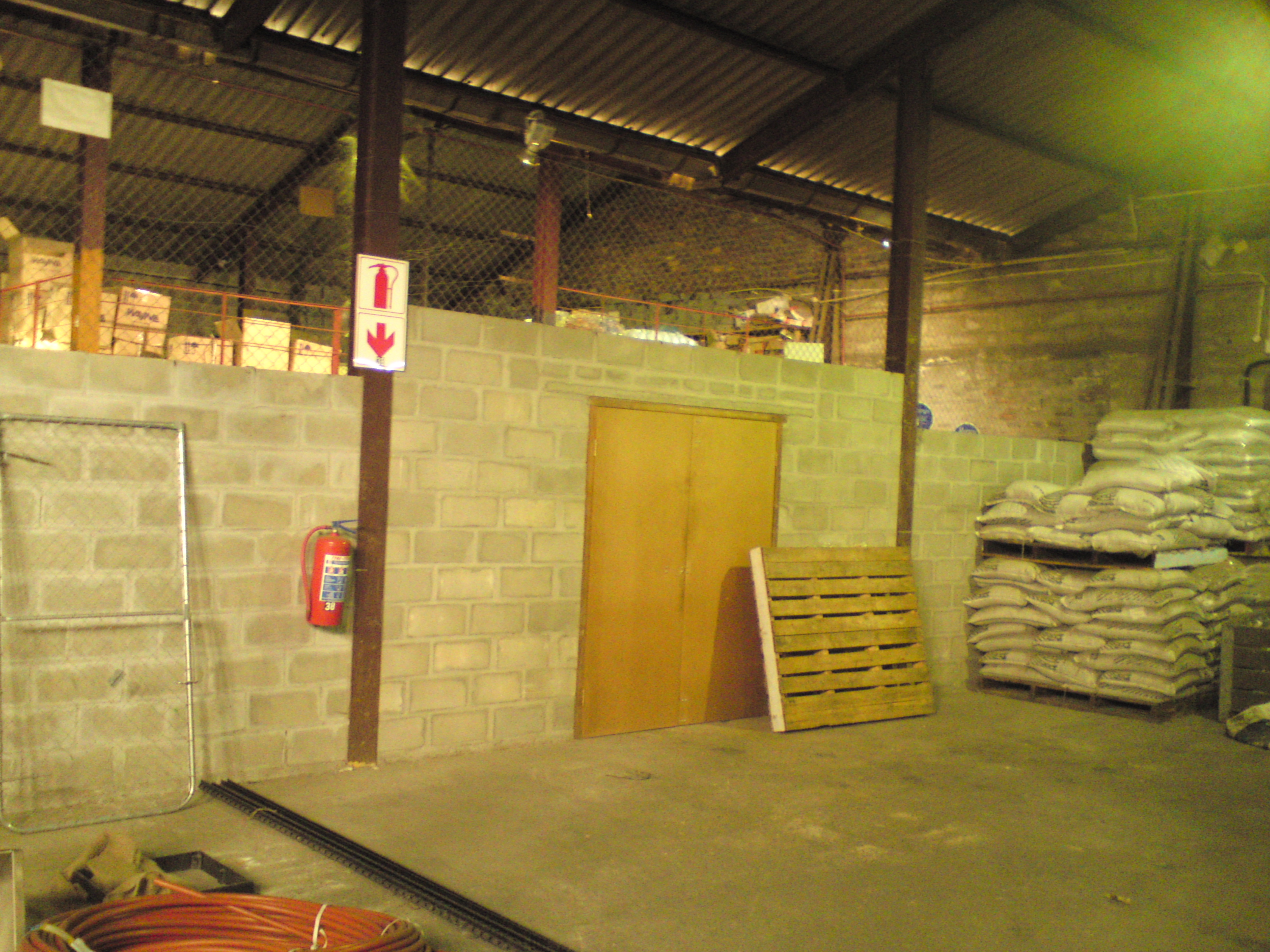
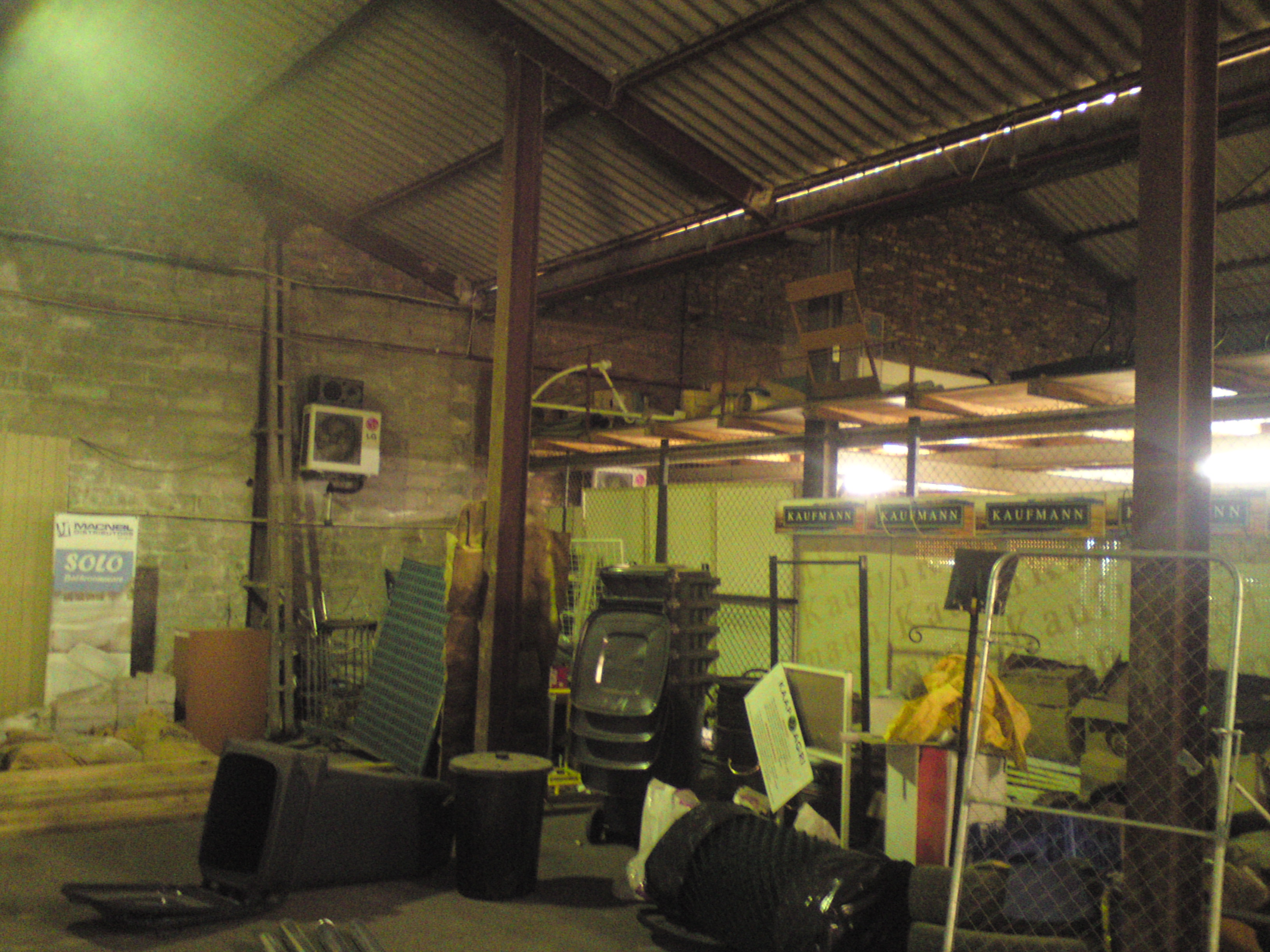
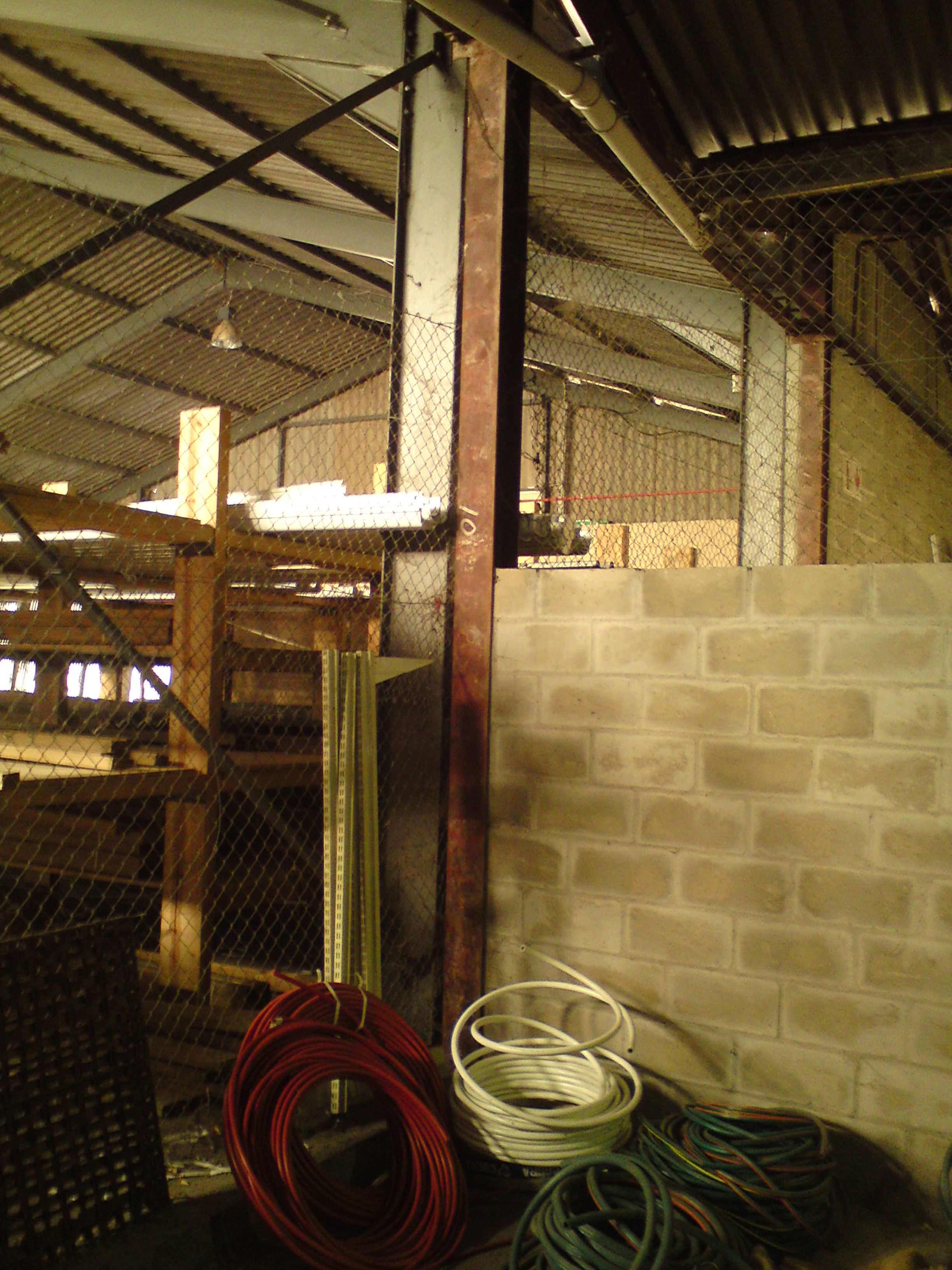
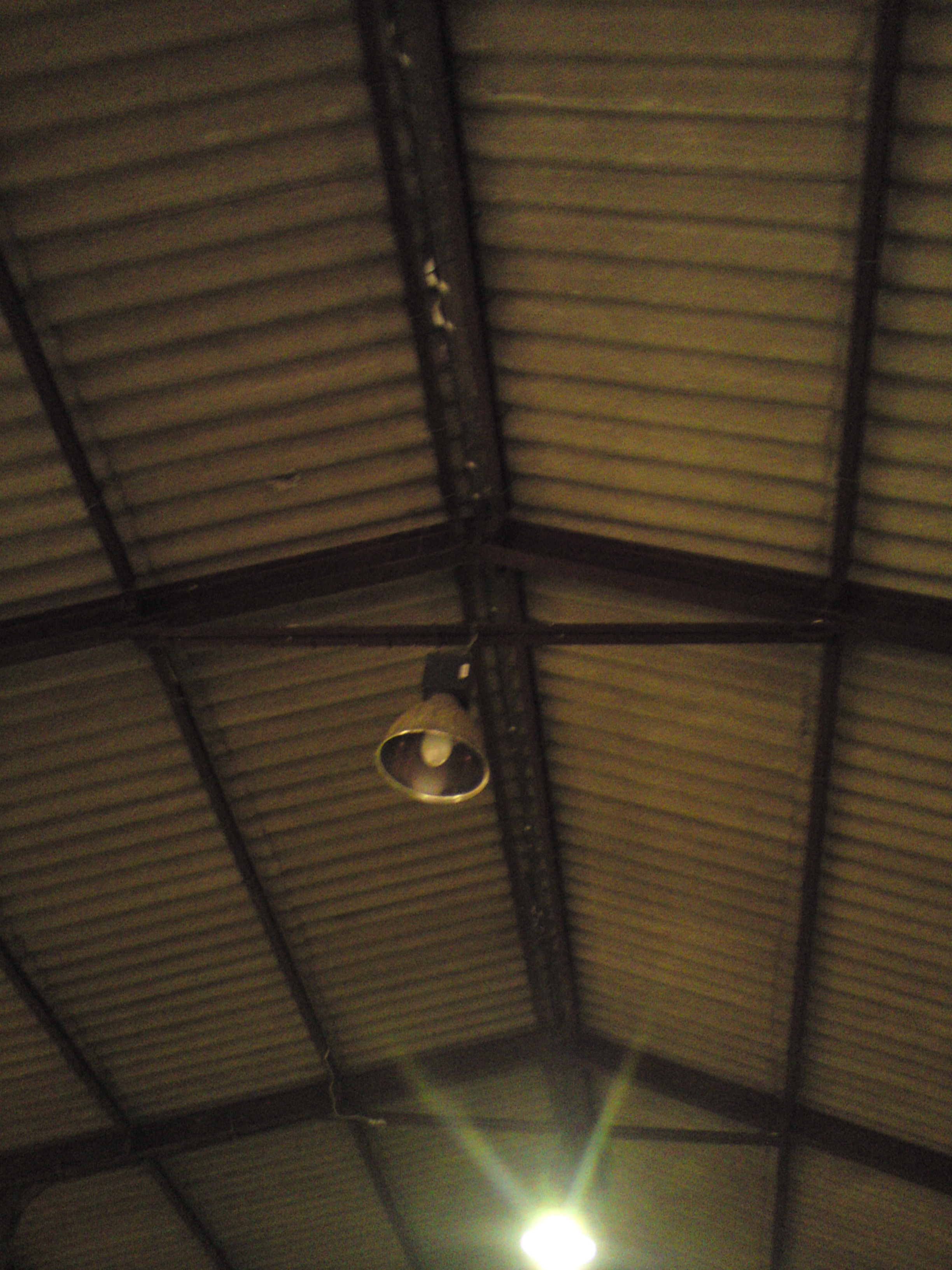
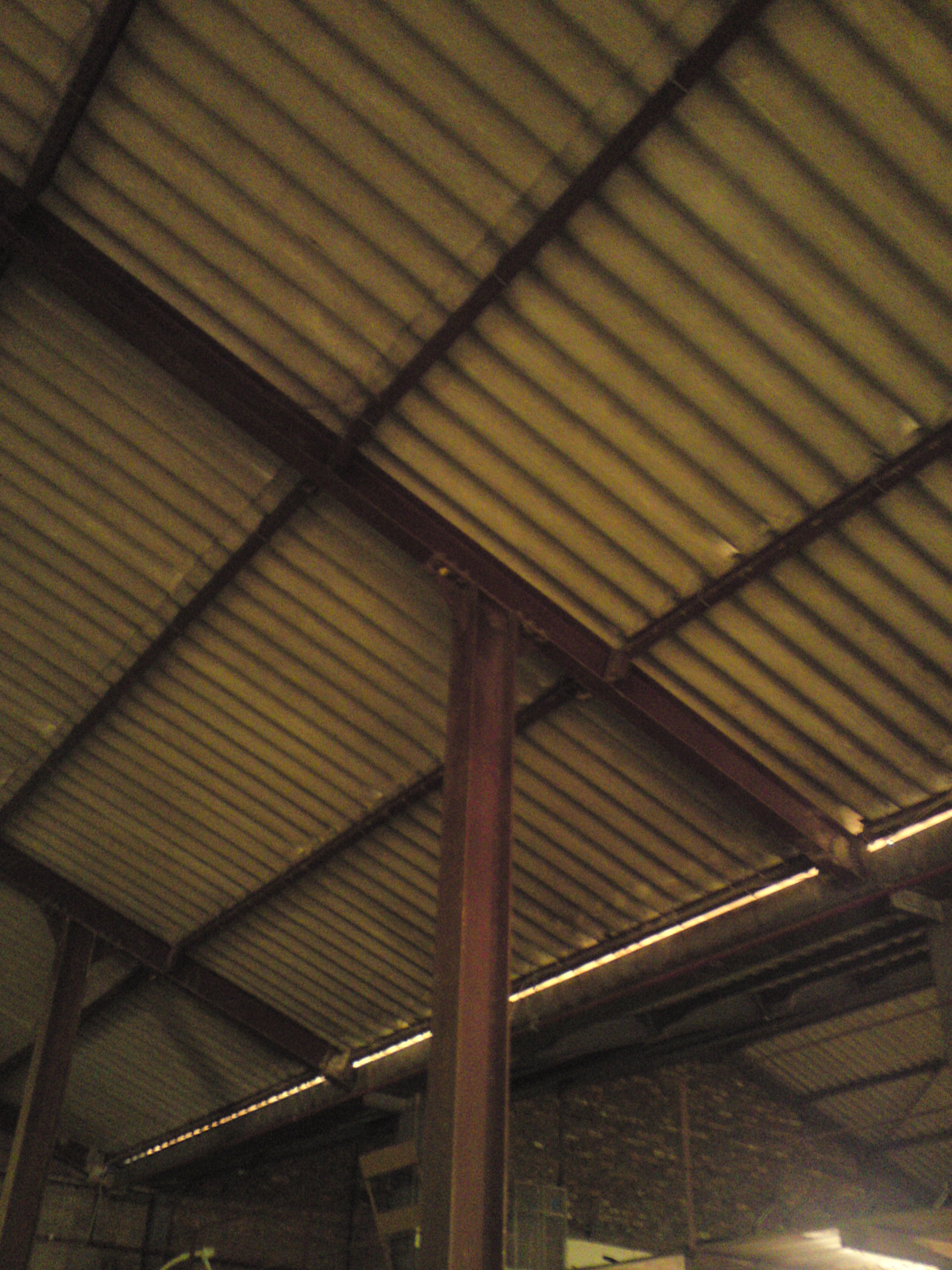
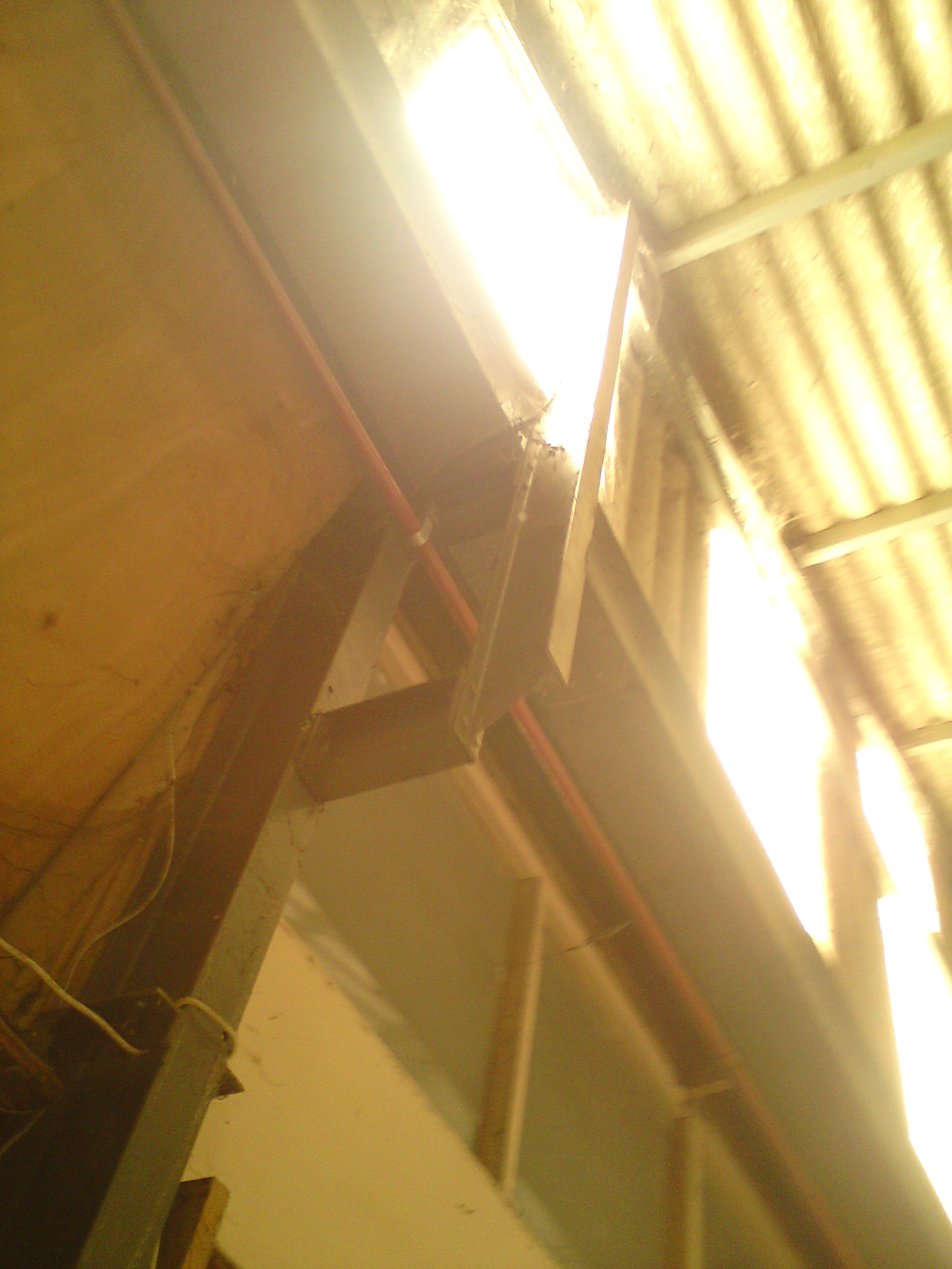
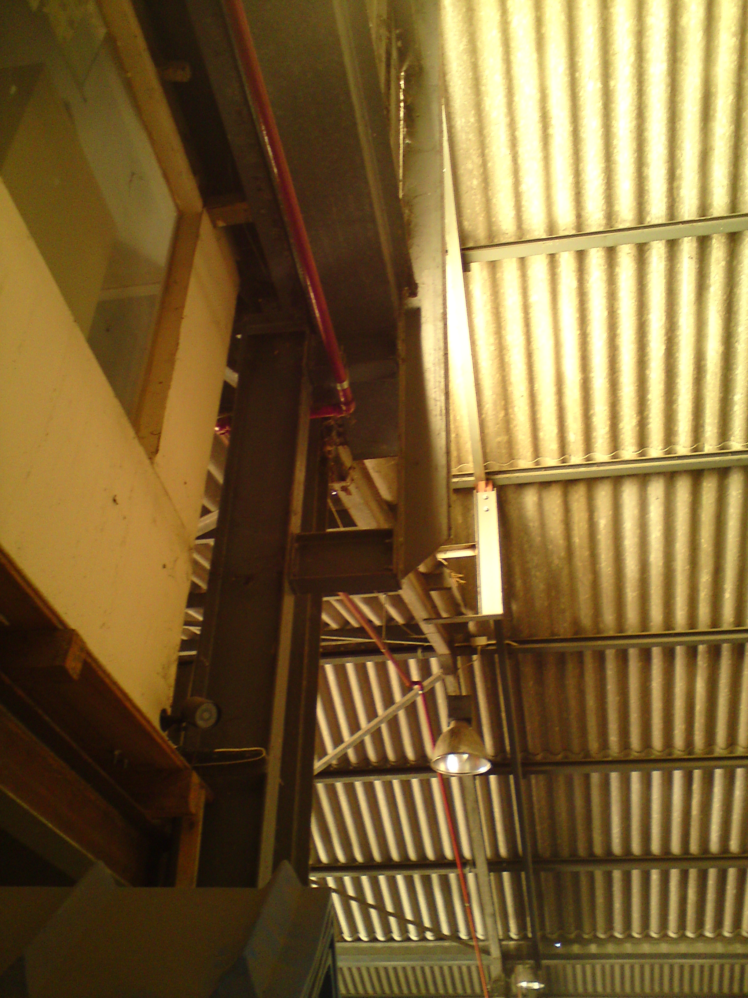
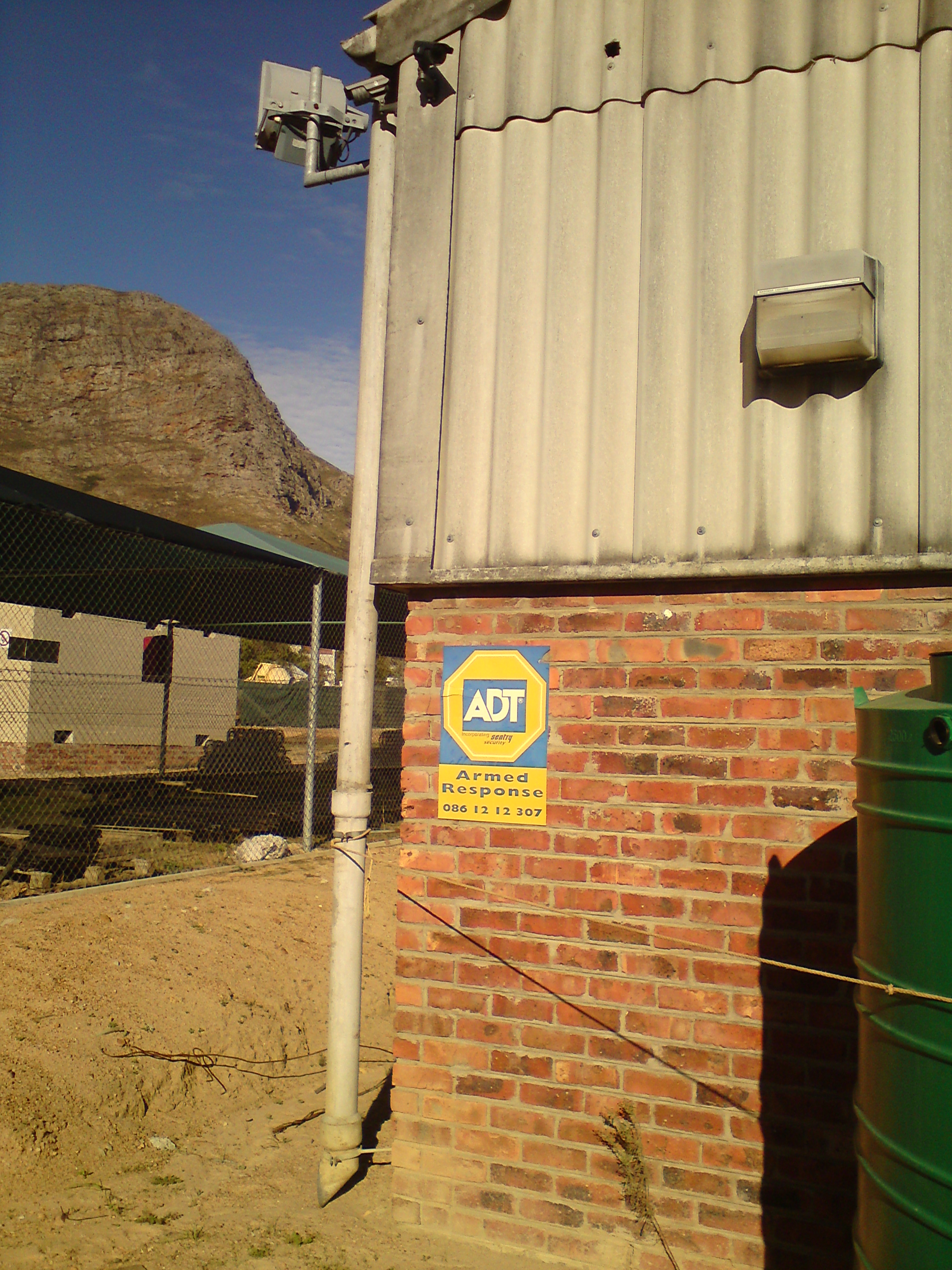
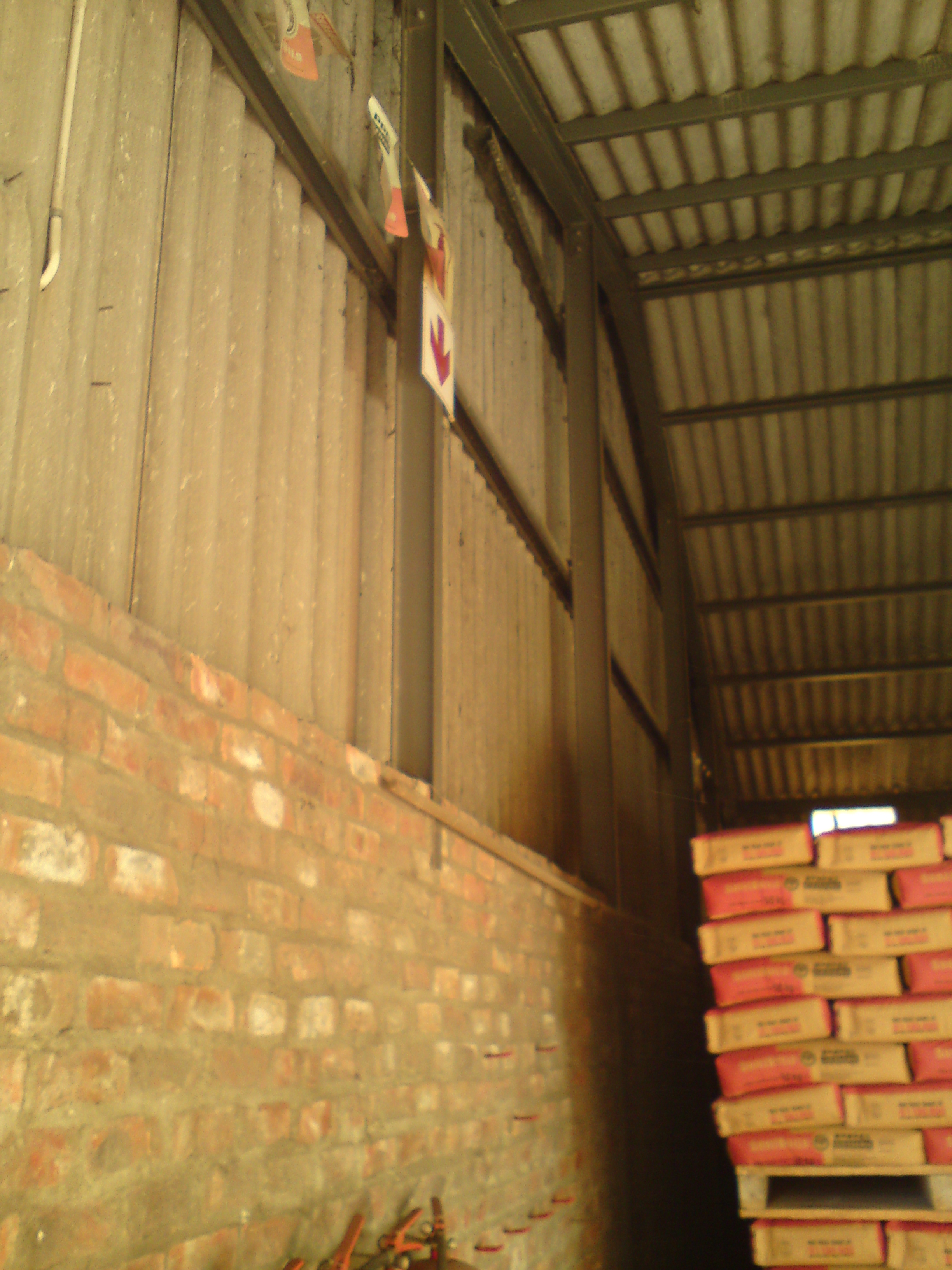
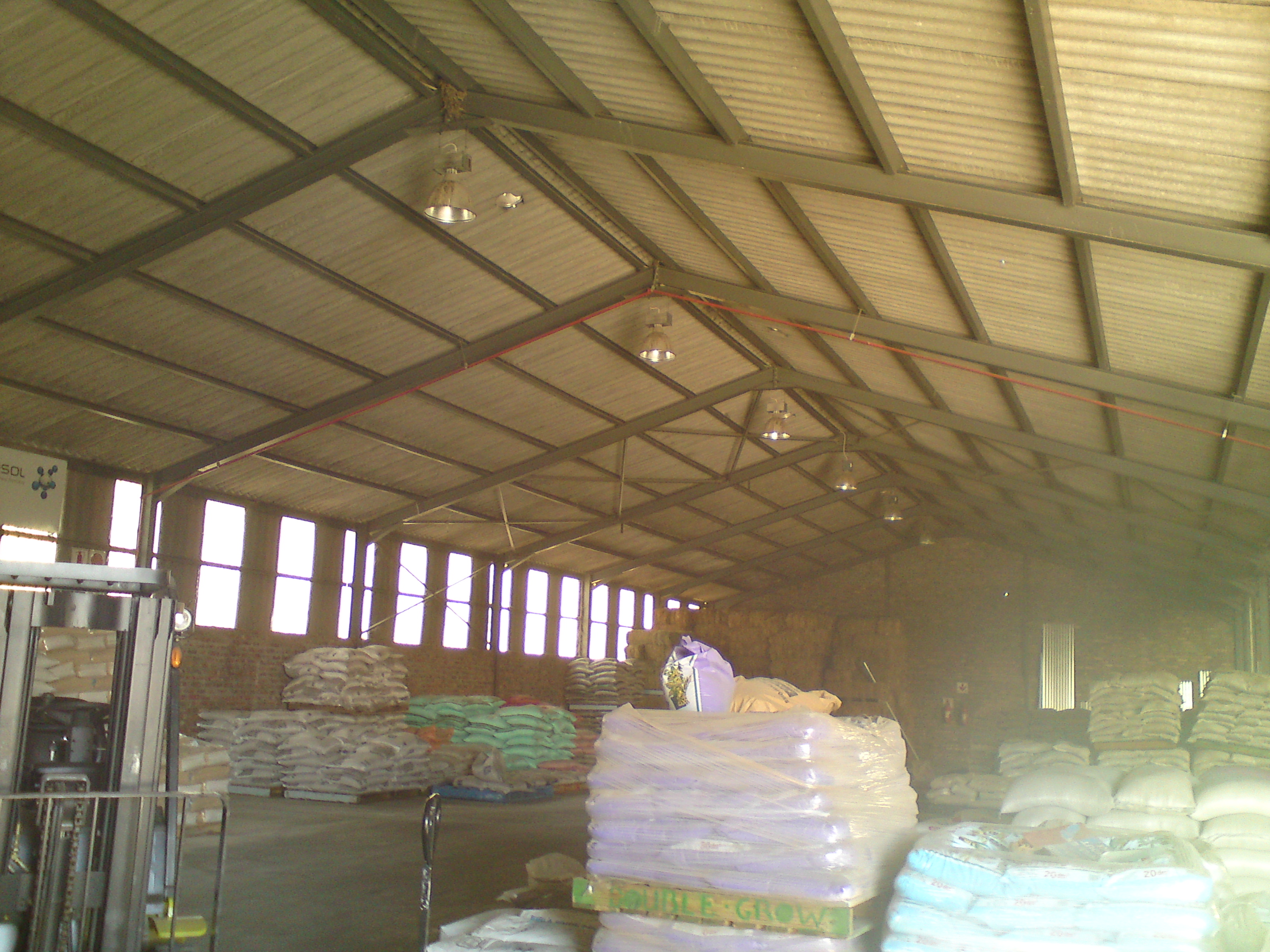
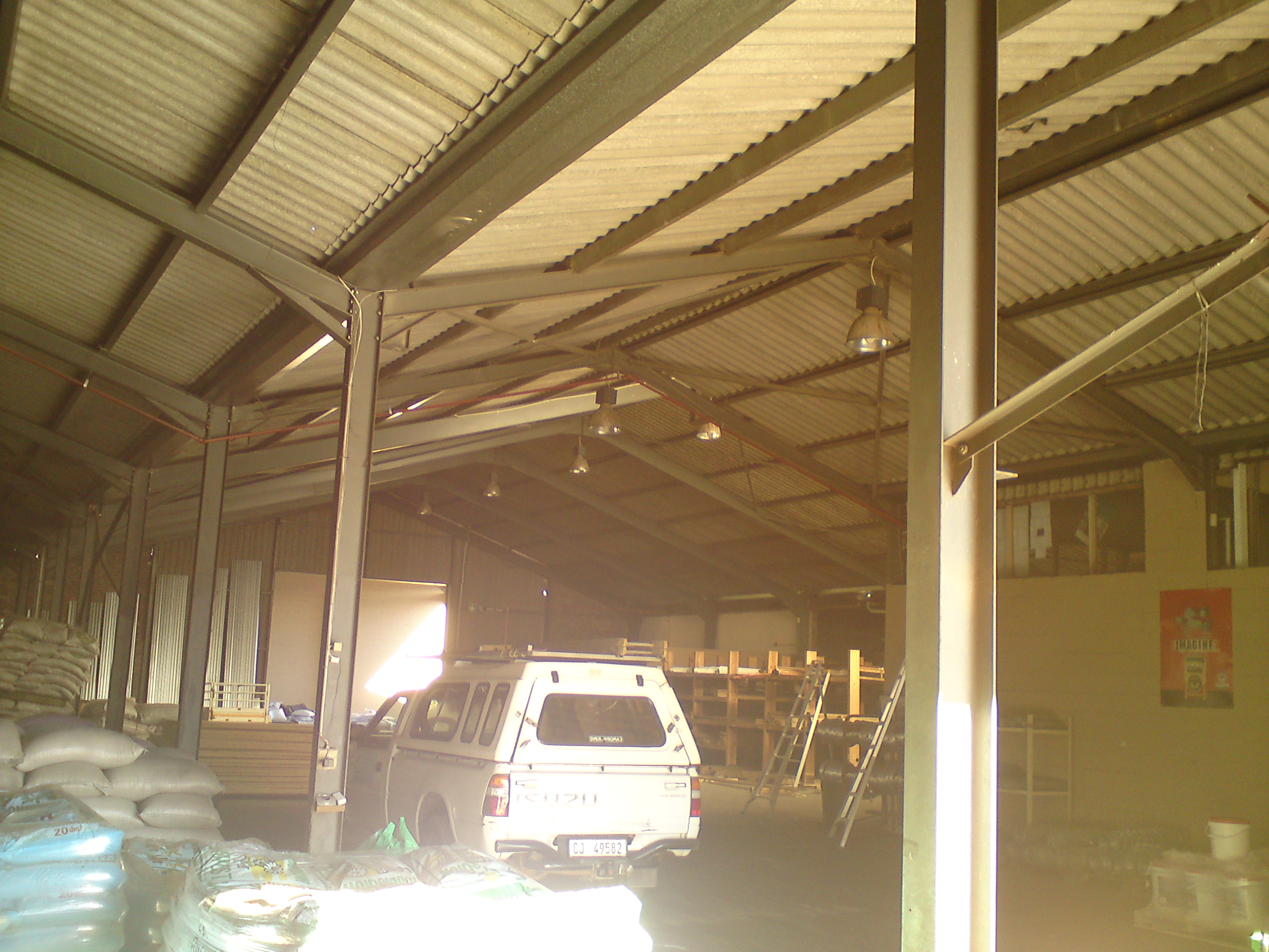
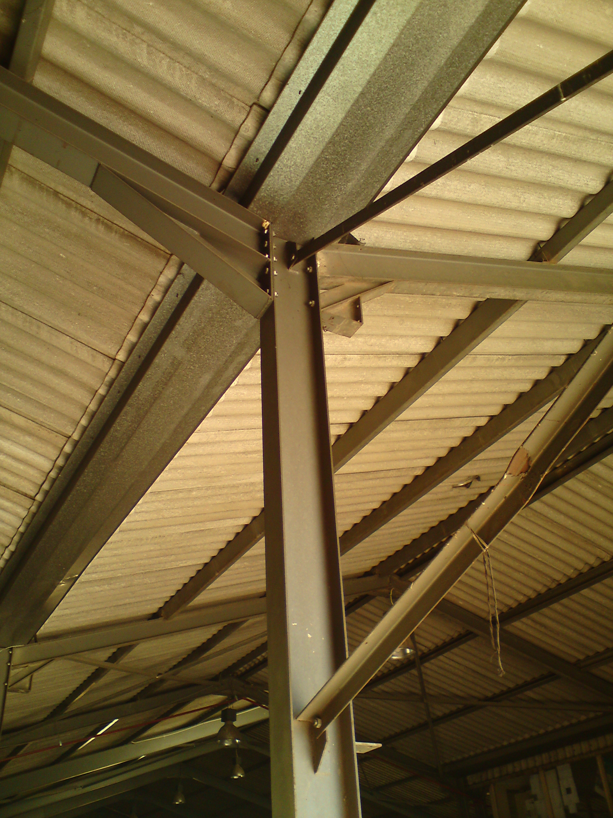
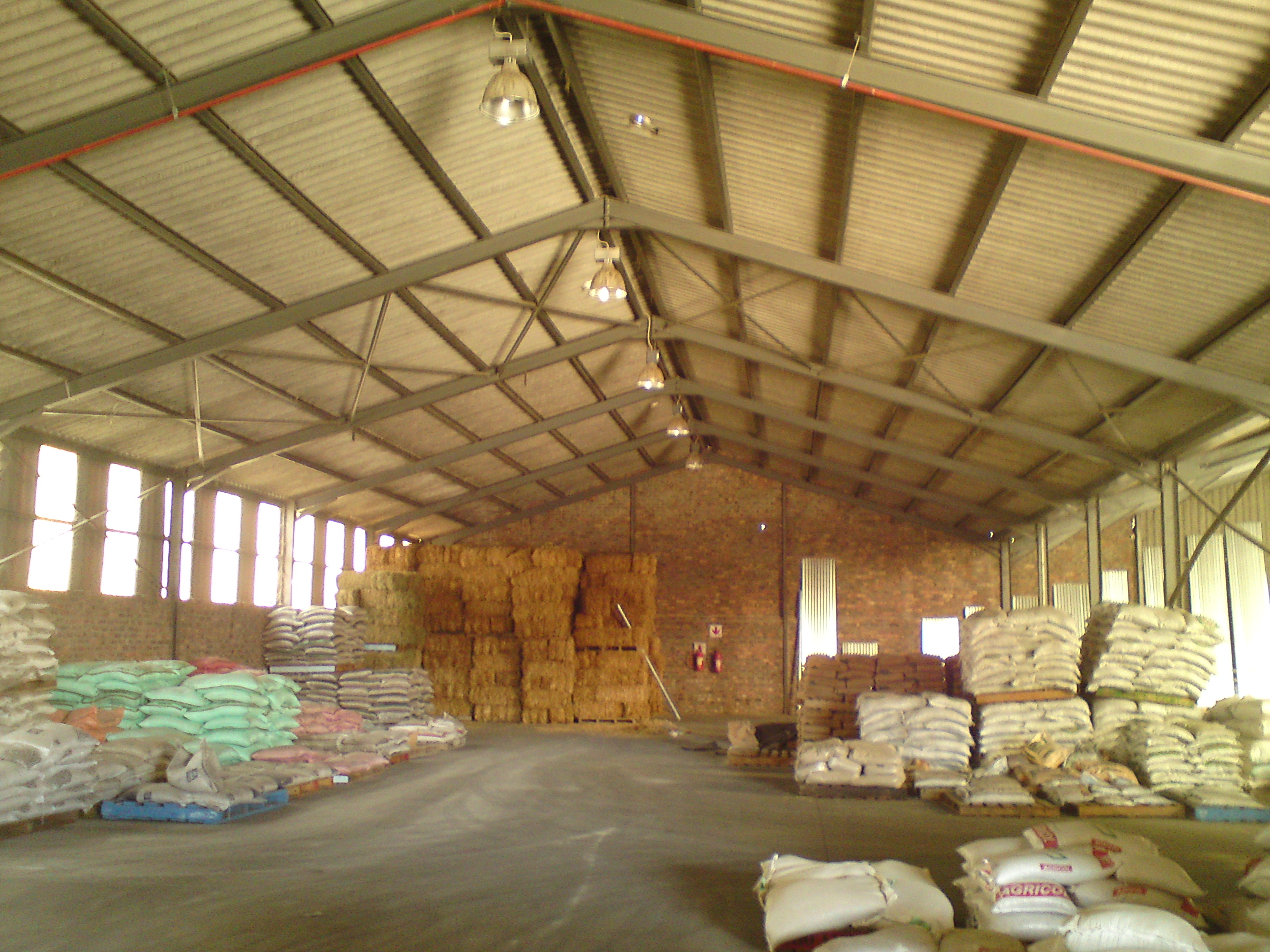
The above pictures are pictures of the site in Franschoek which I took.
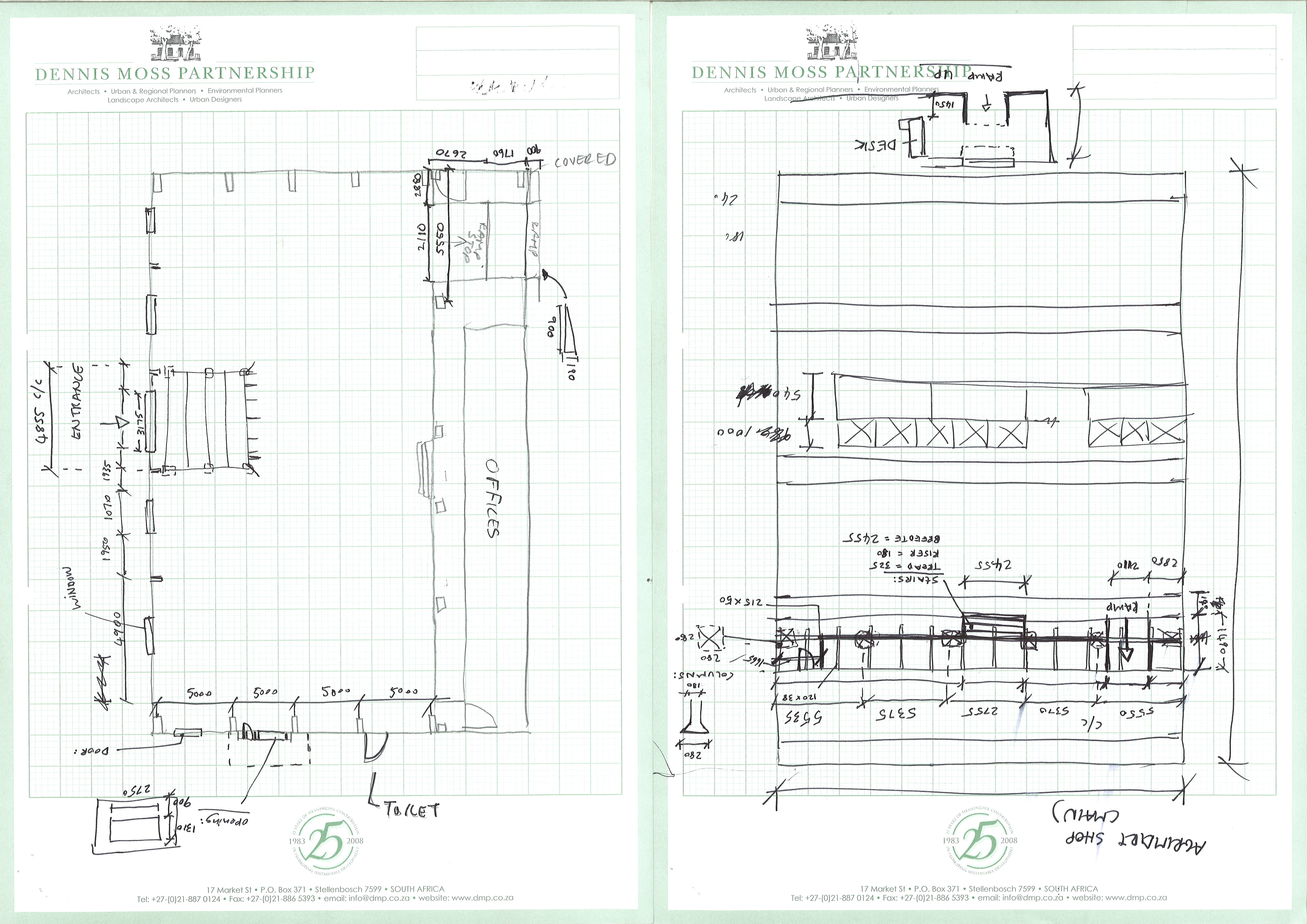
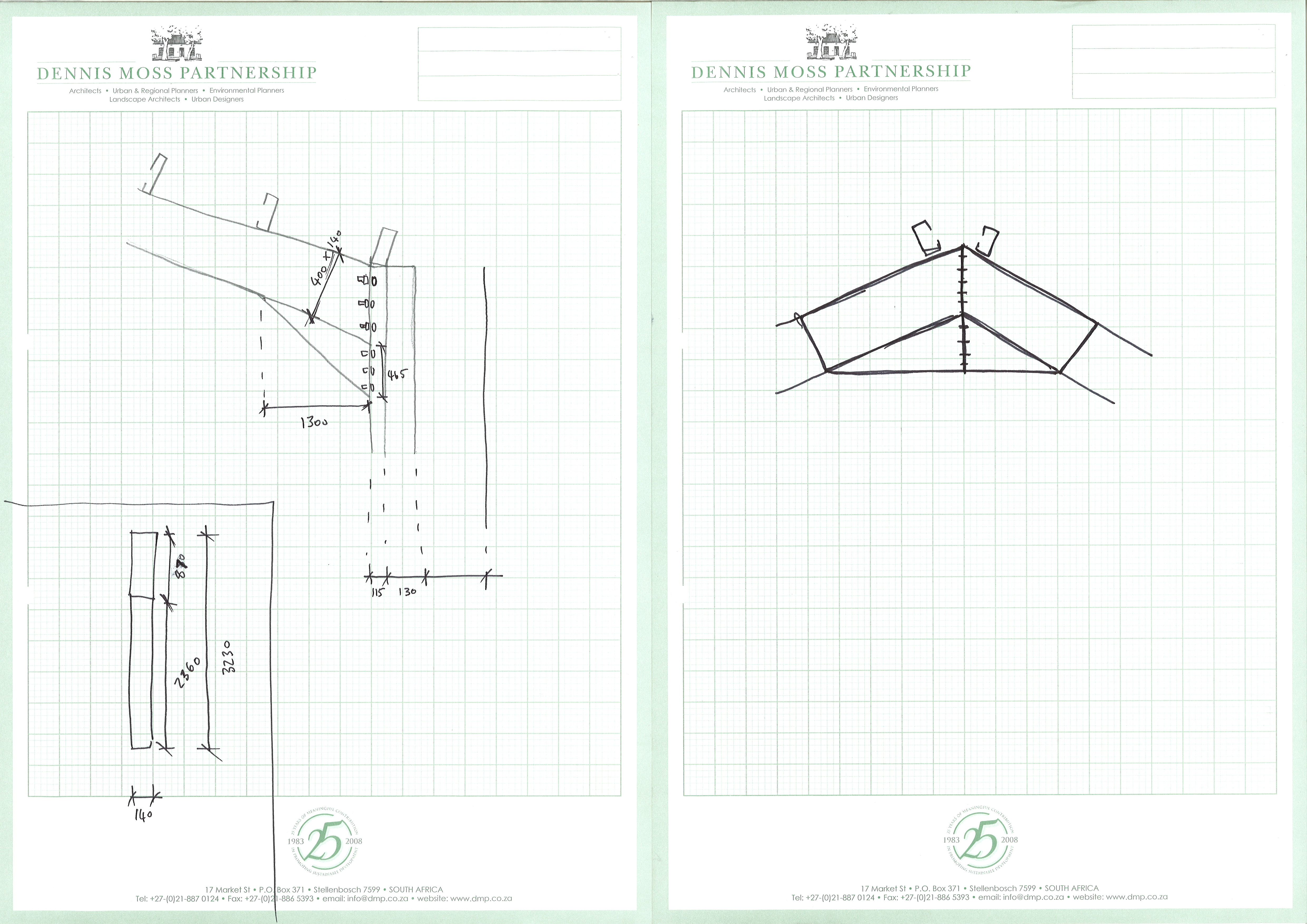
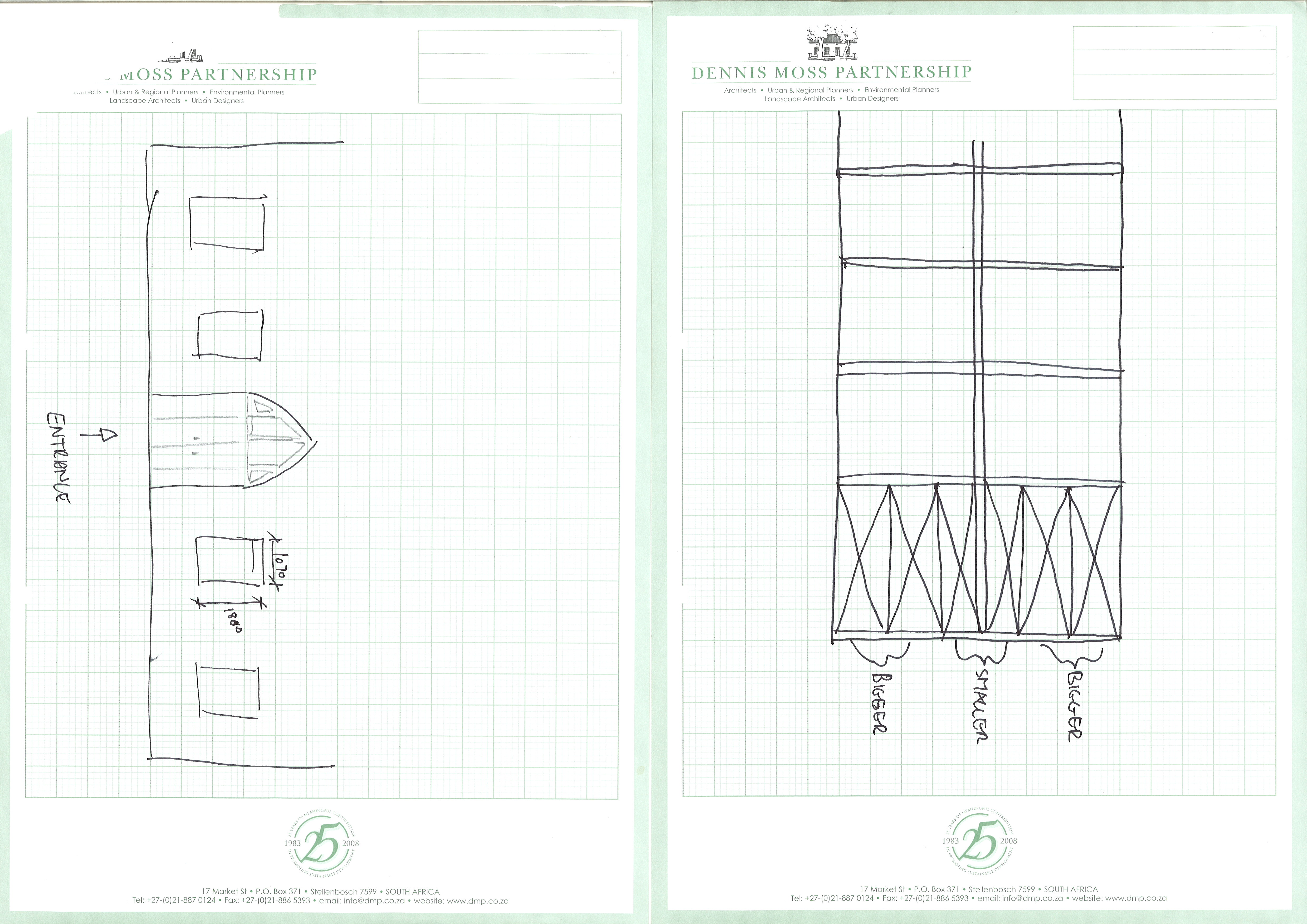
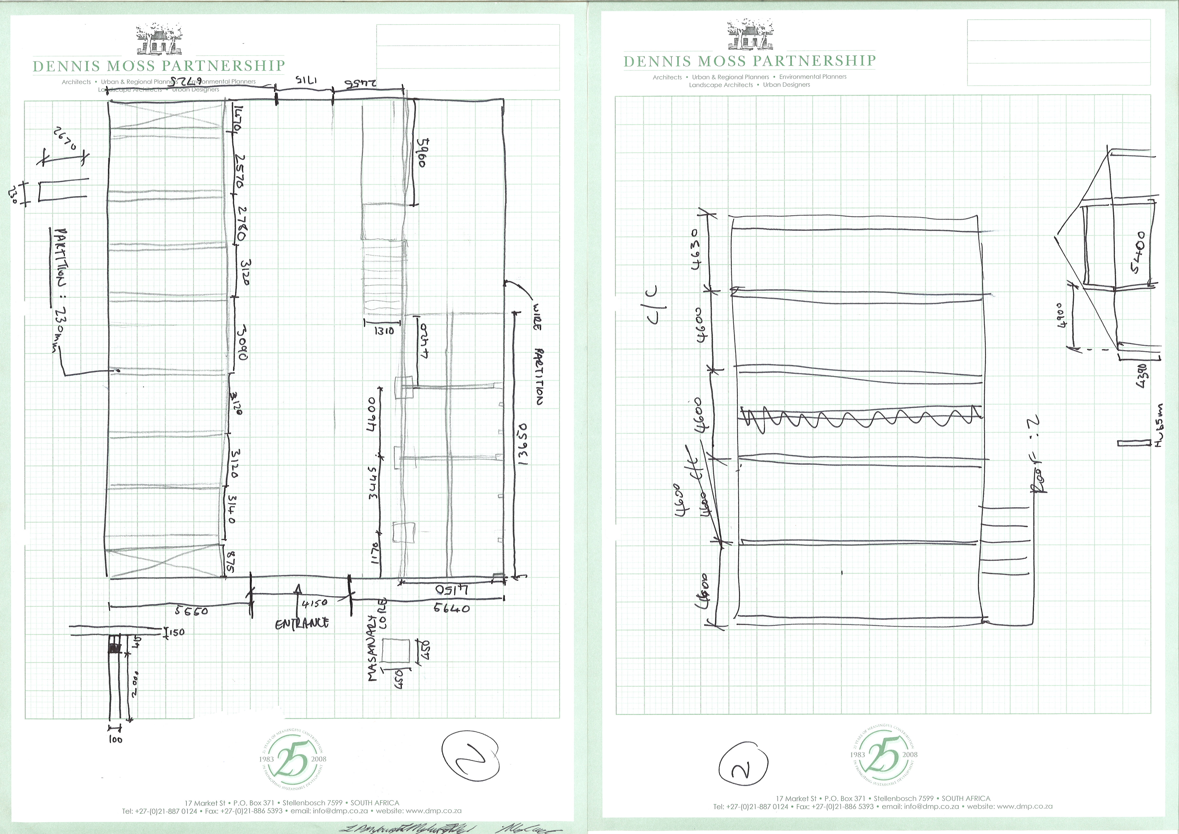
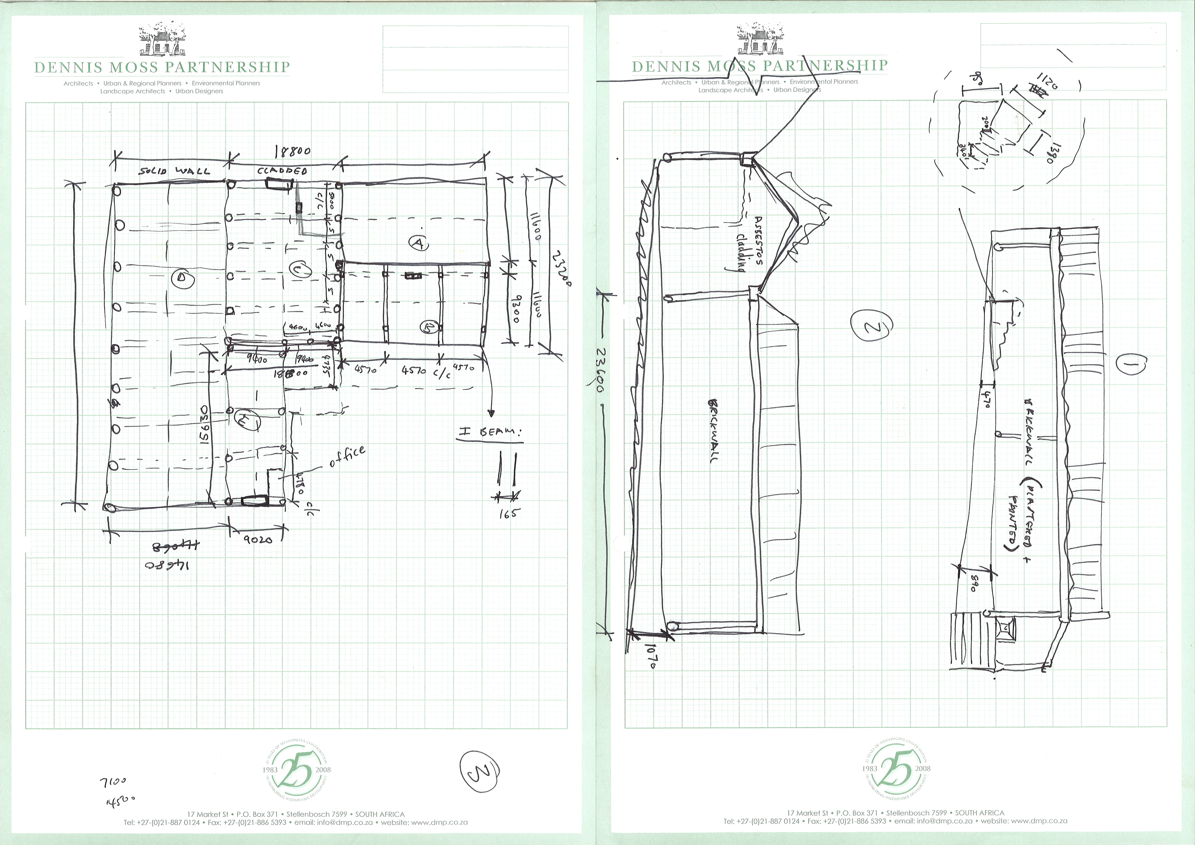
This is a retail development project that is situated in Franschoek. The site already has an existing Agrimark store which will remain on site while adding other shops and a spar onto the site. Myself and Aubrey Langeveldt had to go measure up this Agrimark store and because it was a steel frame structure, we had to draw up the positions of the steel beams so that the construction could take place around that frame structure. The above pictures are the measured up drawings we took while on our site visit to Franschoek.
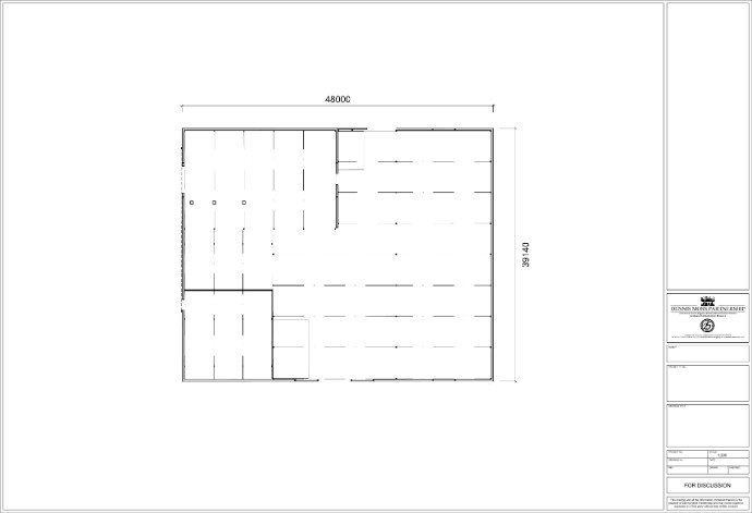
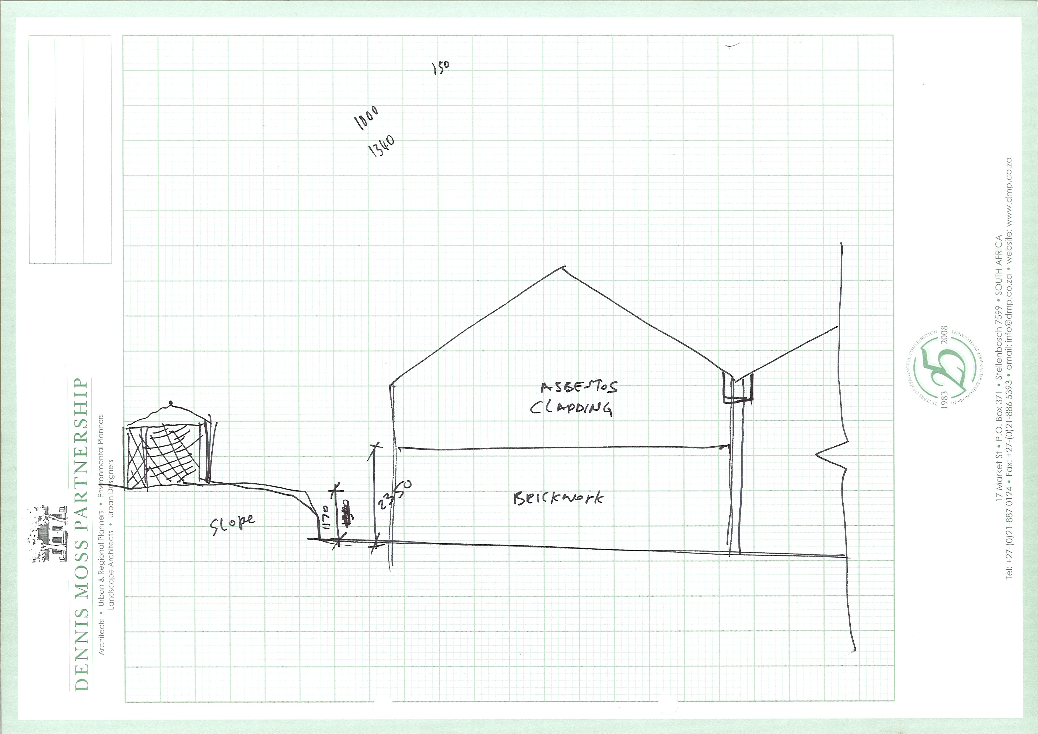
With all the measurements taken myself and Aubrey had to draw up our measurements in Auto CAD. The above picture is the section I drew up which comprises of the stores/warehouse of Agrimark. It shows the placement of the steel beams and the basic roof structure of the stores.
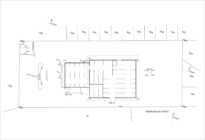
After we were done with our separate CAD drawings I was given the task of putting the two parts of the structure together so that it could be placed on the site plan which was given by the engineer. This was for the purpose of seeing whether or not that the plans we received from the engineers were the same as our measured up drawings. With a few minor adjustments the plan corresponded with each other. The area within the stippled lines is my drawing which I drew up in Auto CAD.
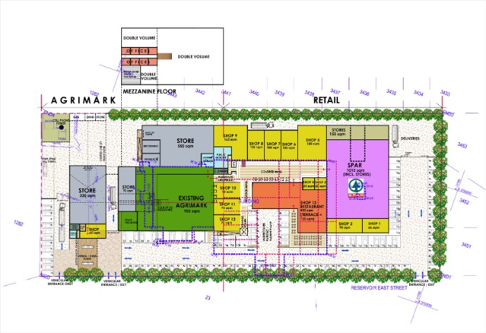
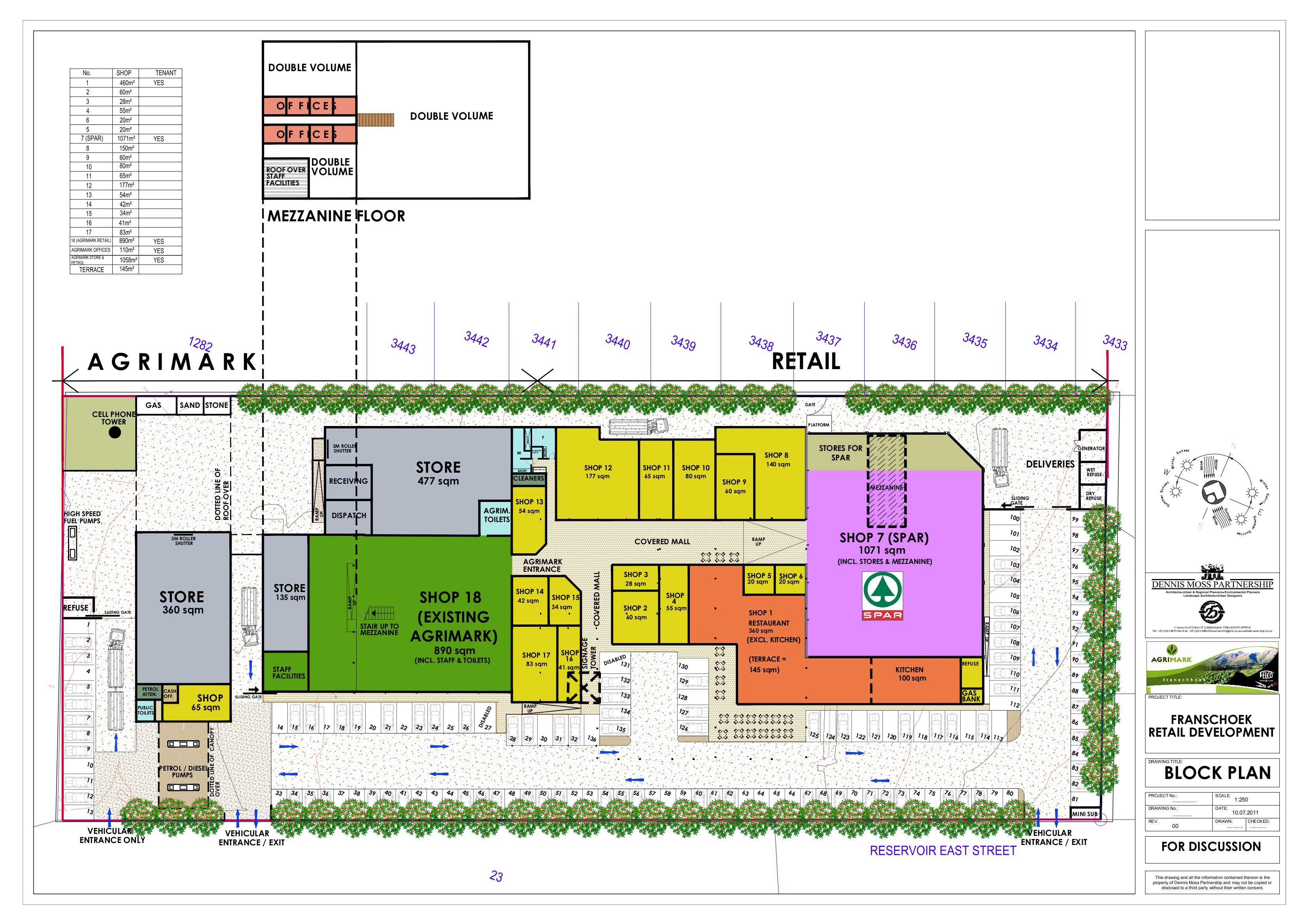
The above drawing is the proposed layout for the client to show the development changes. I never drew this up, It was done by one of the senior architects at our firm. The blue stippled line shows the existing Agrimark store. I was asked to put the measured up drawing on this plan so that the
placement of the steel beams could be seen so that the senior architect
could design with the steel beams in mind. I then had to clean up this drawing and to make a few changes to the layout. I was asked to do this a couple times and the latest proposal is below.
I had to create a area table of all the shops and had to place the drawing into a title block. This is the drawing that was submitted to the client for there approval. |
WORKING DRAWINGS
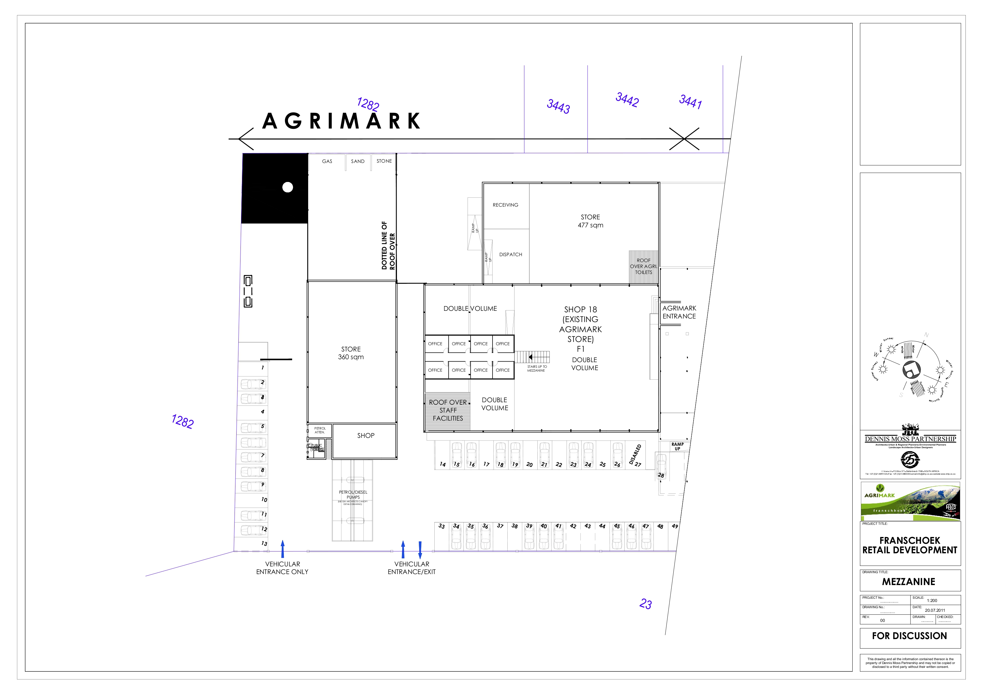
These are the most current drawings of the Franchoek developement plan. I had to take the existing Agrimark and draw the walls of the existing and new to idicate what has changed. The drawing with the stippled lines is a demolition plan which I had to draw up to indicate which parts of the existing structure would be demolished.
Q & A
1) What is the purpose of the drawing/information?
2) Who are the people for whom you have prepared the drawing/information?
3) Are there any other ways to provide the same drawing/information?
4) Explain the purpose of every component of the drawing/information mean (for example, why do you put certain dimensions on a specific drawing?)
1) The purpose of the site visit was to measure up the site and structure so that a plan can be compiled. The block plan is a proposed layout for the retail developement. It is done this way so that the plan can manipulated to what the clients want. 2) The drawing is for the clients who will be the owners of the proposed shops. Eg: Spar, Agrimark, Mr. Video and a restaurant to name a few.3) The drawing can be more detailed but it is purely for experimentle purposes to allow for adjustment to the plan. 4) The existing concrete beams are put on the plan so that the design of the extensions can be designed with the beams in mind. Trying to use the existing steel frame structure as much as possible which would reduce the price of the structure. The different hatches shows the different floor surfaces fo the site and the blue arrows shows the movement of traffic within the developement. The sqaure metered number is to show the client how much area they will have in there store. The drawings entail all relevant information to represent to the client.
UPCOMING HOUSE
I had to draw up the walls of a future house on a grid so that the further design of the house could take place. |
|

.jpg)
-A1.jpg)
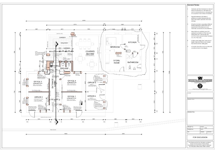
STIAS
I did not do the complete drawing but the parts indicated in the revision clouds are the parts that I did. I made some revisions to an existing plan as well as add a few extra dimensions. |
This free website was made using Yola.
No HTML skills required. Build your website in minutes.
Go to www.yola.com and sign up today!
Make a free website with Yola